Armada e500 Power Supply - Compaq Notebook PC
Armada e500 Power Supply
View Results Below
Free Compaq Armada e500 manuals!
Problems with Compaq Armada e500?
Ask a Question
Free Compaq Armada e500 manuals!
Problems with Compaq Armada e500?
Ask a Question
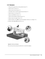
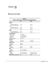
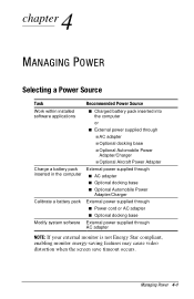
Related Manual Pages


Similar Questions

Which Power Supply Can You Replace On A Compaq Preserio R1000
(Posted by sefton2306 9 years ago)

How To Dismount Hp Compaq Nc8230 Power Supply
(Posted by flygujj 9 years ago)

I Want Schematic Diagram For Specific Area Of Dc Power Supply Adaptor Socket
(Posted by Egypt 11 years ago)