Instruction Manual
Page 2
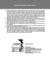
... an equilateral triangle, is located on the unit rear panel and the other than that contained in the literature accompanying the appliance. Retain this information for use by qualified service personnel only. Model No. To reduce the risk of the supplied power cord to the power jack on the rear of important operating and maintenance (servicing) instructions in the operating instructions unless you are for future...
... an equilateral triangle, is located on the unit rear panel and the other than that contained in the literature accompanying the appliance. Retain this information for use by qualified service personnel only. Model No. To reduce the risk of the supplied power cord to the power jack on the rear of important operating and maintenance (servicing) instructions in the operating instructions unless you are for future...
Instruction Manual
Page 3
...instructions, may not cause harmful interference, and •• This device must be required to stop operation of the television. If this television contains millions of thin film transistors that to which can radiate radio frequency energy and, if not installed and used in a residential installation. LCD Information The LCD panel used in accordance with Class B limits in Subpart B of Part 15...radio or television reception, which the receiver is connected. •• Consult the dealer or an experienced radio/TV technician for help Use of shielded cable is encouraged...
...instructions, may not cause harmful interference, and •• This device must be required to stop operation of the television. If this television contains millions of thin film transistors that to which can radiate radio frequency energy and, if not installed and used in a residential installation. LCD Information The LCD panel used in accordance with Class B limits in Subpart B of Part 15...radio or television reception, which the receiver is connected. •• Consult the dealer or an experienced radio/TV technician for help Use of shielded cable is encouraged...
Instruction Manual
Page 4
... defeat the safety purpose of the polarized plug. 1111 Power-Cord Protection: Power supply cords should be routed so that could result in the vicinity of overhead power lines or other electric light or power circuits, or where it is left unattended and unused for long periods of time. Use only with carts, stands, tripods, brackets, or tables recommended by the manufacturer. 1111 Lightning...
... defeat the safety purpose of the polarized plug. 1111 Power-Cord Protection: Power supply cords should be routed so that could result in the vicinity of overhead power lines or other electric light or power circuits, or where it is left unattended and unused for long periods of time. Use only with carts, stands, tripods, brackets, or tables recommended by the manufacturer. 1111 Lightning...
Instruction Manual
Page 5
... National Electrical Code, ANS/NFPA 70 provides information with regard to proper grounding of the mast and supporting structure, grounding of the lead-in wire to an antenna-discharge unit, size of grounding conductors, location of antenna-discharge unit, connection to grounding electrodes, and requirements for service. 2222 Replacement Parts: When replacement parts are covered by the operating instructions as improper adjustment of other controls may...
... National Electrical Code, ANS/NFPA 70 provides information with regard to proper grounding of the mast and supporting structure, grounding of the lead-in wire to an antenna-discharge unit, size of grounding conductors, location of antenna-discharge unit, connection to grounding electrodes, and requirements for service. 2222 Replacement Parts: When replacement parts are covered by the operating instructions as improper adjustment of other controls may...
Instruction Manual
Page 7
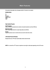
... 500 lines. Multiple Mode TV AV S-VIDEO COMPONENT HDMI VGA High Quality Property High Resolution Adopt an MPEG2 decoding format to experience some light or dark spots appearing on the LCD screen. 1 Main Features This product incorporates the LCD display and the TV receiver in Dolby Digital decoder to output high quality sound effects. Screen Support the picture size of a normal screen (4:3) and a wide screen (16:9) LCD (Liquid Crystal Display) Designed with color TFT liquid crystal...
... 500 lines. Multiple Mode TV AV S-VIDEO COMPONENT HDMI VGA High Quality Property High Resolution Adopt an MPEG2 decoding format to experience some light or dark spots appearing on the LCD screen. 1 Main Features This product incorporates the LCD display and the TV receiver in Dolby Digital decoder to output high quality sound effects. Screen Support the picture size of a normal screen (4:3) and a wide screen (16:9) LCD (Liquid Crystal Display) Designed with color TFT liquid crystal...
Instruction Manual
Page 8
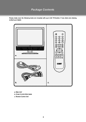
a, Main Unit b, Power Cord & RCA Cable c, Remote Control Unit 2 c. If any items are included with your dealer. a. b. Package Contents Please make sure the following items are missing, contact your LCD TV/monitor.
a, Main Unit b, Power Cord & RCA Cable c, Remote Control Unit 2 c. If any items are included with your dealer. a. b. Package Contents Please make sure the following items are missing, contact your LCD TV/monitor.
Instruction Manual
Page 9
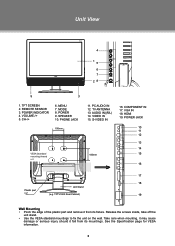
... IN 18. TFT SCREEN 2. REMOTE SENSOR 3. MENU 7. SPEAKER 10. MODE 8. TV ANTENNA 13. COMPONENT IN 17. HDMI 19. POWER JACK 10 11 12 13 14 15 16 17 18 19 Wall Mounting •• Pinch the edge of the plastic part and remove it fall from its mountings. CH-/+ 6. VOLUME-/+ 5. VIDEO IN 15. Unit View 4 15 6 7 28 9 3 1. AUDIO IN((R/L) 14. S-VIDEO IN < > > VESA Standard mounting thread x 4 < 100mm > Plastic part x 2 Unit Stand (e.g. Take care when mounting, it may cause damage...
... IN 18. TFT SCREEN 2. REMOTE SENSOR 3. MENU 7. SPEAKER 10. MODE 8. TV ANTENNA 13. COMPONENT IN 17. HDMI 19. POWER JACK 10 11 12 13 14 15 16 17 18 19 Wall Mounting •• Pinch the edge of the plastic part and remove it fall from its mountings. CH-/+ 6. VOLUME-/+ 5. VIDEO IN 15. Unit View 4 15 6 7 28 9 3 1. AUDIO IN((R/L) 14. S-VIDEO IN < > > VESA Standard mounting thread x 4 < 100mm > Plastic part x 2 Unit Stand (e.g. Take care when mounting, it may cause damage...
Instruction Manual
Page 10
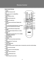
.... POWER Press to muffle/release sound. 20. MENU Press to locate the previously viewed channel. 13. RETURN Press to show the channel list. 19. CHANNEL +/- VOLUME +/- FORMAT 9 19 20 Press to show the setup menu. 12 5. CH-LIST Press to change the sound mode. 4 MODE Press to show the Favorite Channel List. CC 1 10 Set the CC mode. (CC on /off. 2. FAV Press to adjust the volume. 11 4. Press to show the current working mode. (TV, AV, S-VIDEO, COMPONENT, HDMI...
.... POWER Press to muffle/release sound. 20. MENU Press to locate the previously viewed channel. 13. RETURN Press to show the channel list. 19. CHANNEL +/- VOLUME +/- FORMAT 9 19 20 Press to show the setup menu. 12 5. CH-LIST Press to change the sound mode. 4 MODE Press to show the Favorite Channel List. CC 1 10 Set the CC mode. (CC on /off. 2. FAV Press to adjust the volume. 11 4. Press to show the current working mode. (TV, AV, S-VIDEO, COMPONENT, HDMI...
Instruction Manual
Page 11
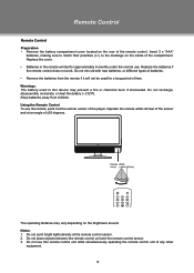
... sensor and at the remote control sensor. 222 Do not place objects between the remote control unit and the remote control sensor. 333 Do not use this device may vary depending on the rear of ±30 degrees. 7 s MODE RETURN The operating distance may present a fire or chemical burn if mistreated. Notes: 111 Do not point bright lights directly at an angle of the remote control. Replace...
... sensor and at the remote control sensor. 222 Do not place objects between the remote control unit and the remote control sensor. 333 Do not use this device may vary depending on the rear of ±30 degrees. 7 s MODE RETURN The operating distance may present a fire or chemical burn if mistreated. Notes: 111 Do not point bright lights directly at an angle of the remote control. Replace...
Instruction Manual
Page 12
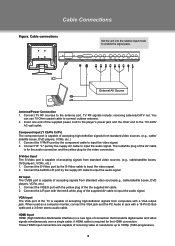
Cable connections Set the unit into the relative input mode to the antenna port. External AV Source Antenna/Power Connection 111 Connect TV RF sources to enable the signal pass. The red/white plug of the supplied power cord to the player's power jack and the other end to input the audio signal. When used as a computer moniter, connect the VGA jack and the PC Audio In jack with the red & white plug of the supplied AV cable to the 110-240V AC wall outlet. You can...
Cable connections Set the unit into the relative input mode to the antenna port. External AV Source Antenna/Power Connection 111 Connect TV RF sources to enable the signal pass. The red/white plug of the supplied power cord to the player's power jack and the other end to input the audio signal. When used as a computer moniter, connect the VGA jack and the PC Audio In jack with the red & white plug of the supplied AV cable to the 110-240V AC wall outlet. You can...
Instruction Manual
Page 13
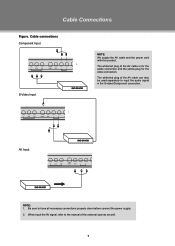
The white/red plug of the external sources as well. 7 AV Input NOTE: 111 Be sure to have all necessary connections properly done before connect the power supply. 222 When input the AV signal, refer to input the audio signal in the S-video/Component connection. The white/red plug of the AV cable can also be used separately to the manual of the AV cable is for the audio connection and the yellow plug for the video connection. Cable Connections Figure. Cable connections Component Input S-Video Input NOTE: We supply the AV cable and the power cord with this product.
The white/red plug of the external sources as well. 7 AV Input NOTE: 111 Be sure to have all necessary connections properly done before connect the power supply. 222 When input the AV signal, refer to input the audio signal in the S-video/Component connection. The white/red plug of the AV cable can also be used separately to the manual of the AV cable is for the audio connection and the yellow plug for the video connection. Cable Connections Figure. Cable connections Component Input S-Video Input NOTE: We supply the AV cable and the power cord with this product.
Instruction Manual
Page 14
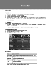
... TV signal mode. 444 Press the CH+/- buttons to exit/back up menu. TV Setup Menu Various features can press the number buttons to scan channels under the Channel Menu. TV Function TV Function Preparations 111 Connect the cables.(Refer to the "Cable Connections" section for details. Warm Picture Menu ITEM Picture Mode Contrast Brightness Color Tint Sharpness Color Mode DESCRIPTION Setup the picture mode (Personal, Standard, Dynamic, Soft). See the "Channel Menu" section for details). 222 Press the POWER button to turn on the player...
... TV signal mode. 444 Press the CH+/- buttons to exit/back up menu. TV Setup Menu Various features can press the number buttons to scan channels under the Channel Menu. TV Function TV Function Preparations 111 Connect the cables.(Refer to the "Cable Connections" section for details. Warm Picture Menu ITEM Picture Mode Contrast Brightness Color Tint Sharpness Color Mode DESCRIPTION Setup the picture mode (Personal, Standard, Dynamic, Soft). See the "Channel Menu" section for details). 222 Press the POWER button to turn on the player...
Instruction Manual
Page 15
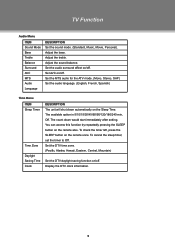
.../15/30/45/60/90/120/180/240 min, Off. To check the timer left, press the SLEEP button on the remote also. Adjust the treble. You can access this function by repeatedly pressing the SLEEP button on the remote once. Display the DTV clock information. 9 Set the MTS audio for the ATV mode. (Mono, Stereo, SAP) Set the audio language. (English, French, Spanish) Time Menu ITEM Sleep Timer Time Zone...
.../15/30/45/60/90/120/180/240 min, Off. To check the timer left, press the SLEEP button on the remote also. Adjust the treble. You can access this function by repeatedly pressing the SLEEP button on the remote once. Display the DTV clock information. 9 Set the MTS audio for the ATV mode. (Mono, Stereo, SAP) Set the audio language. (English, French, Spanish) Time Menu ITEM Sleep Timer Time Zone...
Instruction Manual
Page 16
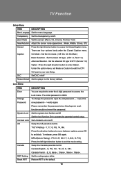
... type to access the Lock menu. Setup the Canada parental control Canada English - TV Function Setup Menu ITEM DESCRIPTION Menu Language Set the menu language. Zoom Mode Set the screen effect. (4:3, Cinema, Normal, 16:9) Noise Reduction Adjust the screen noise appearance. (Weak, Middle, Strong, Off) Closed Press the right direction button to enter Option. Lock Menu ITEM Enter Change Password System Lock Unrated Lock US Canada RRT Setting Reset RRT DESCRIPTION You are four options lised under the Closed Caption menu...
... type to access the Lock menu. Setup the Canada parental control Canada English - TV Function Setup Menu ITEM DESCRIPTION Menu Language Set the menu language. Zoom Mode Set the screen effect. (4:3, Cinema, Normal, 16:9) Noise Reduction Adjust the screen noise appearance. (Weak, Middle, Strong, Off) Closed Press the right direction button to enter Option. Lock Menu ITEM Enter Change Password System Lock Unrated Lock US Canada RRT Setting Reset RRT DESCRIPTION You are four options lised under the Closed Caption menu...

Instruction Manual
Page 17
... AUTO, STD, IRC and HRC before scaning. Press the left /right direction button to change characters. When use the Channel No option or directly locate the channel by the number button/CH+/- In the Show/ Hide menu, press the up /down direciton button to select the channel, press OK to hide the channel, press OK again to release. AV Function Channel Menu ITEM DESCRIPTION Air/Cable Setup...
... AUTO, STD, IRC and HRC before scaning. Press the left /right direction button to change characters. When use the Channel No option or directly locate the channel by the number button/CH+/- In the Show/ Hide menu, press the up /down direciton button to select the channel, press OK to hide the channel, press OK again to release. AV Function Channel Menu ITEM DESCRIPTION Air/Cable Setup...
Instruction Manual
Page 18
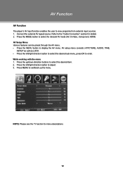
... direction buttons to select the desired item. 222 Press the left /right direction button to select the desired sub-menu, press OK to display the AV menu. AV setup menu consists of PICTURE, AUDIO, TIME, SETUP as well as LOCK. •• Press the left /right direction button to adjust. 333 Press MENU to view programs from external input sources. 111 Connect the external AV signal source. Refer to the "Cable Connection" section for menu descriptions 12...
... direction buttons to select the desired item. 222 Press the left /right direction button to select the desired sub-menu, press OK to display the AV menu. AV setup menu consists of PICTURE, AUDIO, TIME, SETUP as well as LOCK. •• Press the left /right direction button to adjust. 333 Press MENU to view programs from external input sources. 111 Connect the external AV signal source. Refer to the "Cable Connection" section for menu descriptions 12...
Instruction Manual
Page 19
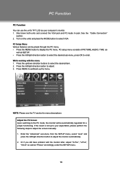
... for a proper functioning. See the "Cable Connection" section. 222 Turn on the units and press the MODE button to select VGA PC Setup Menu Various features can use the unit's TFT LCD as "Phase" accordingly under the SETUP menu. 13 NOTE: Please see the TV section for menu descriptions Adjust the PC Screen Upon switching to enter. While working with the monitor after, adjust "H-Pos", "V-Pos", "Clock" as well...
... for a proper functioning. See the "Cable Connection" section. 222 Turn on the units and press the MODE button to select VGA PC Setup Menu Various features can use the unit's TFT LCD as "Phase" accordingly under the SETUP menu. 13 NOTE: Please see the TV section for menu descriptions Adjust the PC Screen Upon switching to enter. While working with the monitor after, adjust "H-Pos", "V-Pos", "Clock" as well...
Instruction Manual
Page 20
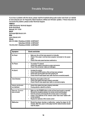
... AV video signal input cable is connected properly. •• Check if the system has been properly connected. •• If using antenna, adjust the antenna. •• Make sure the POWER button on the unit has been turned on manually. •• Remove the obstacles between the remote control and the player. •• Point the remote control towards the remote sensor on the player and the restore function should reset the player. 14...
... AV video signal input cable is connected properly. •• Check if the system has been properly connected. •• If using antenna, adjust the antenna. •• Make sure the POWER button on the unit has been turned on manually. •• Remove the obstacles between the remote control and the player. •• Point the remote control towards the remote sensor on the player and the restore function should reset the player. 14...
Instruction Manual
Page 21
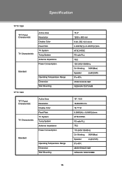
... 1923 Operating Temperature Range Dimension Wall Mounting TFT Panel Characteristic TV Charactoristic Active Area Resolution Display Color Pixel Pitch TV System Tuing System Antenna Impedance Power Consumption Standard Operating Temperature Range Dimension Wall Mounting 15.4" 1280 x 800 mm 6-bit, 262.144 colors 0.25875(H) x 0.25875(V)mm ATSC/NTSC FS with PLL 75Ω 100-240V 50/60Hz On Working 30W(Max) Speaker 2x(4Ω,5W) 0ºc-40ºc 378X133X334 MM VESA M4...
... 1923 Operating Temperature Range Dimension Wall Mounting TFT Panel Characteristic TV Charactoristic Active Area Resolution Display Color Pixel Pitch TV System Tuing System Antenna Impedance Power Consumption Standard Operating Temperature Range Dimension Wall Mounting 15.4" 1280 x 800 mm 6-bit, 262.144 colors 0.25875(H) x 0.25875(V)mm ATSC/NTSC FS with PLL 75Ω 100-240V 50/60Hz On Working 30W(Max) Speaker 2x(4Ω,5W) 0ºc-40ºc 378X133X334 MM VESA M4...
Instruction Manual
Page 22
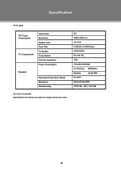
Specification TFTV 2224 TFT Panel Characteristic TV Charactoristic Active Area Resolution Display Color Pixel Pitch TV System Tuing System Antenna Impedance Power Consumption Standard Operating Temperature Range Dimension Wall Mounting 22" 1680x1050 mm 16.77 M 0.282(H) x 0.282(V)mm ATSC/NTSC FS with PLL 75Ω 110-240V 50/60Hz On Working 60W(Max) Speaker 2x(4Ω,5W) 0ºc-40ºc 527x167x444 MM VESA M4, 100 X 100 MM P/N: 907-FV15-2400-00R Specifications and manual are subject to change without prior notice. 16
Specification TFTV 2224 TFT Panel Characteristic TV Charactoristic Active Area Resolution Display Color Pixel Pitch TV System Tuing System Antenna Impedance Power Consumption Standard Operating Temperature Range Dimension Wall Mounting 22" 1680x1050 mm 16.77 M 0.282(H) x 0.282(V)mm ATSC/NTSC FS with PLL 75Ω 110-240V 50/60Hz On Working 60W(Max) Speaker 2x(4Ω,5W) 0ºc-40ºc 527x167x444 MM VESA M4, 100 X 100 MM P/N: 907-FV15-2400-00R Specifications and manual are subject to change without prior notice. 16


