Instruction Manual
Page 9
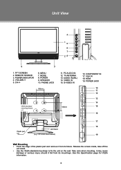
...edge of the plastic part and remove it fall from its mountings. CH-/+ 6. SPEAKER 10. PHONE JACK 100mm 11. PC AUDIO IN 12. TV ANTENNA 13. HDMI 19. See the Specification page for VESA informaiton. 3 MENU 7. POWER 9. AUDIO IN((R/L) 14. COMPONENT IN 17. Release the... screws inside, take off the unit stand. •• Use the VESA standard mountings to fix the unit on the wall. TFTV1923 Rear Cabinet) 16. VOLUME-/+ 5. REMOTE SENSOR 3. Unit View ...
...edge of the plastic part and remove it fall from its mountings. CH-/+ 6. SPEAKER 10. PHONE JACK 100mm 11. PC AUDIO IN 12. TV ANTENNA 13. HDMI 19. See the Specification page for VESA informaiton. 3 MENU 7. POWER 9. AUDIO IN((R/L) 14. COMPONENT IN 17. Release the... screws inside, take off the unit stand. •• Use the VESA standard mountings to fix the unit on the wall. TFTV1923 Rear Cabinet) 16. VOLUME-/+ 5. REMOTE SENSOR 3. Unit View ...


