User Manual
Page 2
English ÂÂ Table of Contents Location of Controls and Parts 3 Getting Started...5 Power Supply...5 Battery Back-Up...5 Setting the Correct Time...5 Operation...6 Using the Radio...6 Using the Alarm Timer (Wake to Radio or Buzzer 6 Snooze (Delayed Alarm)...7 Sleep or Sleep-and-Wake to Radio 7 Auxiliary Audio Input From External Device 8 Specifications...9 Troubleshooting & Support 10 Safety Notices...12 Page 2 Table Of Contents
English ÂÂ Table of Contents Location of Controls and Parts 3 Getting Started...5 Power Supply...5 Battery Back-Up...5 Setting the Correct Time...5 Operation...6 Using the Radio...6 Using the Alarm Timer (Wake to Radio or Buzzer 6 Snooze (Delayed Alarm)...7 Sleep or Sleep-and-Wake to Radio 7 Auxiliary Audio Input From External Device 8 Specifications...9 Troubleshooting & Support 10 Safety Notices...12 Page 2 Table Of Contents
User Manual
Page 3
Speaker 4. Function switch 5. Frequency Display 3. Clock button 6. Alarm button 8. LED Display 2. Snooze button Location Of Controls And Parts Page 3 Minute button (M) 10. Hour button (H) 9. Sleep button 7. English ÂÂ Location of Controls and Parts 1.
Speaker 4. Function switch 5. Frequency Display 3. Clock button 6. Alarm button 8. LED Display 2. Snooze button Location Of Controls And Parts Page 3 Minute button (M) 10. Hour button (H) 9. Sleep button 7. English ÂÂ Location of Controls and Parts 1.
User Manual
Page 4
Volume dial (Buzzer On) 12. FM antenna Extend the FM antenna wire [17] and adjust its position for optimum reception. Page 4 Location Of Controls And Parts AM / FM / AUX Switch 13. AUX IN jack 15. Battery compartment 16. Ventilation Slots 17. DO NOT PULL ON OR DETACH THIS WIRE. English 11. Tuning dial 14.
Volume dial (Buzzer On) 12. FM antenna Extend the FM antenna wire [17] and adjust its position for optimum reception. Page 4 Location Of Controls And Parts AM / FM / AUX Switch 13. AUX IN jack 15. Battery compartment 16. Ventilation Slots 17. DO NOT PULL ON OR DETACH THIS WIRE. English 11. Tuning dial 14.
User Manual
Page 5
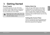
Before connecting to avoid the risk of time. Replace the battery every 6 months for a long period of electric shock. The time will not be preserved in the battery compartment for clock backup (not for radio operation). English ÂÂ Getting Started Power Supply The CRA59 operates from the wall outlet when it is displayed. Getting Started Page 5 Battery Back-Up Install a 9V type 006P battery in the case of this unit matches your local voltage. Setting the Correct Time Hold the CLOCK button [5] and simultaneously press the HOUR button [8] or MINUTE button ...
Before connecting to avoid the risk of time. Replace the battery every 6 months for a long period of electric shock. The time will not be preserved in the battery compartment for clock backup (not for radio operation). English ÂÂ Getting Started Power Supply The CRA59 operates from the wall outlet when it is displayed. Getting Started Page 5 Battery Back-Up Install a 9V type 006P battery in the case of this unit matches your local voltage. Setting the Correct Time Hold the CLOCK button [5] and simultaneously press the HOUR button [8] or MINUTE button ...
User Manual
Page 6
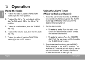
To set the FUNCTION switch [4] to the "OFF" position. —— To wake to buzzer: Turn the VOLUME dial [11] all the way down until the desired time is displayed. 3. To turn the radio on to tune to the desired radio station and set the FUNCTION switch [4] to wake you up . To activate the alarm timer, set the desired volume level. 5. When the clock reaches the set time, the radio or buzzer will light up . To adjust the volume level, turn the TUNING dial [13]. 4. Page 6 Operation Using the Alarm Timer (Wake to a radio station, turn the VOLUME dial [11]. 2. The ALARM SET ON...
To set the FUNCTION switch [4] to the "OFF" position. —— To wake to buzzer: Turn the VOLUME dial [11] all the way down until the desired time is displayed. 3. To turn the radio on to tune to the desired radio station and set the FUNCTION switch [4] to wake you up . To activate the alarm timer, set the desired volume level. 5. When the clock reaches the set time, the radio or buzzer will light up . To adjust the volume level, turn the TUNING dial [13]. 4. Page 6 Operation Using the Alarm Timer (Wake to a radio station, turn the VOLUME dial [11]. 2. The ALARM SET ON...
User Manual
Page 7
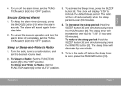
To Sleep to Radio: Set the FUNCTION switch [4] to "1:59" (1 hour and 59 minutes). To turn the alarm timer off the alarm timer, set the desired volume level. 2. Snooze (Delayed Alarm) 1. The sleep timer will increase by one hour to the "OFF" position. To delay the alarm timer (snooze), press the SNOOZE button [10] when the alarm sounds. To activate the Sleep timer, press the SLEEP button [6]. The clock will decrease by one minute. 5. The sleep timer will display "0:59" to the "AUTO" position. 3. To Sleep-and-Wake to Radio: Set the FUNCTION switch [4] to ...
To Sleep to Radio: Set the FUNCTION switch [4] to "1:59" (1 hour and 59 minutes). To turn the alarm timer off the alarm timer, set the desired volume level. 2. Snooze (Delayed Alarm) 1. The sleep timer will increase by one hour to the "OFF" position. To delay the alarm timer (snooze), press the SNOOZE button [10] when the alarm sounds. To activate the Sleep timer, press the SLEEP button [6]. The clock will decrease by one minute. 5. The sleep timer will display "0:59" to the "AUTO" position. 3. To Sleep-and-Wake to Radio: Set the FUNCTION switch [4] to ...
User Manual
Page 8
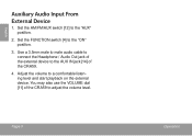
Set the AM/FM/AUX switch [12] to the AUX IN jack [14] of the CRA59. 4. Use a 3.5mm male to male audio cable to connect the Headphone / Audio Out jack of the CRA59 to a comfortable listening level and start playback on the external device. Page 8 Operation Adjust the volume to adjust the volume level. English Auxiliary Audio Input From External Device 1. You may also use the VOLUME dial [11] of the external device to the "AUX" position. 2. Set the FUNCTION switch [4] to the "ON" position. 3.
Set the AM/FM/AUX switch [12] to the AUX IN jack [14] of the CRA59. 4. Use a 3.5mm male to male audio cable to connect the Headphone / Audio Out jack of the CRA59 to a comfortable listening level and start playback on the external device. Page 8 Operation Adjust the volume to adjust the volume level. English Auxiliary Audio Input From External Device 1. You may also use the VOLUME dial [11] of the external device to the "AUX" position. 2. Set the FUNCTION switch [4] to the "ON" position. 3.
User Manual
Page 9
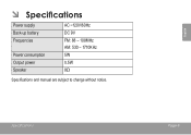
ÂÂ Specifications Power supply Back-up battery Frequencies Power consumption Output power Speaker AC ~120V/60Hz DC 9V FM: 88 - 108MHz AM: 530 - 1710KHz 5W 0.5W 8Ω Specifications and manual are subject to change without notice. Specifications Page 9 English
ÂÂ Specifications Power supply Back-up battery Frequencies Power consumption Output power Speaker AC ~120V/60Hz DC 9V FM: 88 - 108MHz AM: 530 - 1710KHz 5W 0.5W 8Ω Specifications and manual are subject to change without notice. Specifications Page 9 English

User Manual
Page 10
If these resources do not resolve the problem, please contact Technical Support. Address Email Web Phone Coby Electronics Technical Support 150 Knowlton Way Savannah, Georgia 31407 [email protected] www.cobyusa.com 800-727-3592: Monday to Friday, 8:30AM-9:00PM EST Saturday, 9:...
If these resources do not resolve the problem, please contact Technical Support. Address Email Web Phone Coby Electronics Technical Support 150 Knowlton Way Savannah, Georgia 31407 [email protected] www.cobyusa.com 800-727-3592: Monday to Friday, 8:30AM-9:00PM EST Saturday, 9:...
User Manual
Page 11
English The unit does not turn on. Make sure the unit has been powered on manually. Ensure that the volume of CRA59 and/or external device has been set to a reasonable listening level. Make sure the external device has been properly connected to the power outlet and the power supply for the CRA59 is no sound. Ensure that the power cord has been properly connected to CRA59 with an audio cable. Troubleshooting & Support Page 11 There is AC 120V.
English The unit does not turn on. Make sure the unit has been powered on manually. Ensure that the volume of CRA59 and/or external device has been set to a reasonable listening level. Make sure the external device has been properly connected to the power outlet and the power supply for the CRA59 is no sound. Ensure that the power cord has been properly connected to CRA59 with an audio cable. Troubleshooting & Support Page 11 There is AC 120V.

User Manual
Page 12
Model No. For recycling or disposal information about this information for future reference. English ÂÂ Safety Notices For Customer Use: Enter below the serial number that may be of sufficient magnitude to constitute a risk of electric shock. Dangerous high voltage is intended to alert the user to the presence of the unit. The lightning flash with arrowhead symbol within an equilateral triangle is intended to alert the user to rain or moisture. The exclamation point within the product's enclosure that is located on the rear of important operation and servicing ...
Model No. For recycling or disposal information about this information for future reference. English ÂÂ Safety Notices For Customer Use: Enter below the serial number that may be of sufficient magnitude to constitute a risk of electric shock. Dangerous high voltage is intended to alert the user to the presence of the unit. The lightning flash with arrowhead symbol within an equilateral triangle is intended to alert the user to rain or moisture. The exclamation point within the product's enclosure that is located on the rear of important operation and servicing ...
User Manual
Page 13
If this equipment does cause harmful interference to radio or television reception, which the receiver is connected. • Consult the dealer or an experienced radio/TV technician for Class B digital devices, pursuant to Part 15 of the FCC rules. Operation is subject to the following measures: • Reorient or relocate the receiving antenna. • Increase the separation between the equipment and receiver. • Connect the equipment into an outlet on , the user is encouraged to try to correct the interference by one or more of the FCC rules. Note: This equipment has been ...
If this equipment does cause harmful interference to radio or television reception, which the receiver is connected. • Consult the dealer or an experienced radio/TV technician for Class B digital devices, pursuant to Part 15 of the FCC rules. Operation is subject to the following measures: • Reorient or relocate the receiving antenna. • Increase the separation between the equipment and receiver. • Connect the equipment into an outlet on , the user is encouraged to try to correct the interference by one or more of the FCC rules. Note: This equipment has been ...
User Manual
Page 14
Quick stops, excessive force, and uneven surfaces may be routed so that has one direction. Ventilation: Slots and openings in the cabinet are not sure of the type of the product should follow the manufacturer's instructions and should be blocked by placing the product on the rating label. This product should never be followed. 5. For products intended to your home, consult your product dealer or local power company. If you are provided for ventilation to ensure reliable operation of the product and to protect it from overheating.These openings should not be placed ...
Quick stops, excessive force, and uneven surfaces may be routed so that has one direction. Ventilation: Slots and openings in the cabinet are not sure of the type of the product should follow the manufacturer's instructions and should be blocked by placing the product on the rating label. This product should never be followed. 5. For products intended to your home, consult your product dealer or local power company. If you are provided for ventilation to ensure reliable operation of the product and to protect it from overheating.These openings should not be placed ...
User Manual
Page 15
Power Lines: An outside antenna system, extreme care should not be taken to lightning or power-line surges. 15. When installing an outside antenna system should be located in the vicinity of overhead power lines or other hazards. Overloading: Do not overload wall outlets, extension cords, or integral convenience receptacles as the original part. Damage Requiring Service: Unplug this product from the wall outlet and disconnect the antenna or cable system during a lightning storm or when it can result in a fire or electric shock. Page 15 English This will often require ...
Power Lines: An outside antenna system, extreme care should not be taken to lightning or power-line surges. 15. When installing an outside antenna system should be located in the vicinity of overhead power lines or other hazards. Overloading: Do not overload wall outlets, extension cords, or integral convenience receptacles as the original part. Damage Requiring Service: Unplug this product from the wall outlet and disconnect the antenna or cable system during a lightning storm or when it can result in a fire or electric shock. Page 15 English This will often require ...