
Hardware Maintenance Manual
Page 6
... the Power and Cooling Systems 4-2 Troubleshooting the Network Processor Modules and Cables 4-2 Environmental Reporting Features 4-3 Reading Front-Panel LED Indicators 4-3 System LED Operation 4-3 Reading Network Processor Module LED Indicators 4-4 Ethernet Network Processor Module LED Indicators 4-4 Token Ring Network Processor Module LED Indicators 4-5 Four Port Serial Module Indicators 4-6 Dual Serial Network Processor Module LED Indicators 4-7 FDDI Network Processor Module LED...
... the Power and Cooling Systems 4-2 Troubleshooting the Network Processor Modules and Cables 4-2 Environmental Reporting Features 4-3 Reading Front-Panel LED Indicators 4-3 System LED Operation 4-3 Reading Network Processor Module LED Indicators 4-4 Ethernet Network Processor Module LED Indicators 4-4 Token Ring Network Processor Module LED Indicators 4-5 Four Port Serial Module Indicators 4-6 Dual Serial Network Processor Module LED Indicators 4-7 FDDI Network Processor Module LED...

Hardware Maintenance Manual
Page 10
...-Mode Dual-Attachment FDDI Connections 3-13 Cisco 4000 Series DC-Input Power Supply-Rear View 3-20 Cisco 4000 Series AC-Input Power Supply-Rear View 3-20 DC-Input Power Supply Connections 3-21 Cisco 4000 Series-Front Panel Indicators 4-3 Dual-Port Ethernet Network Processor Module LEDs 4-4 Single-Port Ethernet Network Processor Module LEDs 4-4 Token Ring Module Network Connector 4-5 Four-Port Serial Network...
...-Mode Dual-Attachment FDDI Connections 3-13 Cisco 4000 Series DC-Input Power Supply-Rear View 3-20 Cisco 4000 Series AC-Input Power Supply-Rear View 3-20 DC-Input Power Supply Connections 3-21 Cisco 4000 Series-Front Panel Indicators 4-3 Dual-Port Ethernet Network Processor Module LEDs 4-4 Single-Port Ethernet Network Processor Module LEDs 4-4 Token Ring Module Network Connector 4-5 Four-Port Serial Network...

Hardware Maintenance Manual
Page 20
...-CE1). Note The Cisco 4500-M and Cisco 4700 support all network processor modules except the single-port Ethernet network processor module and early versions of a Cisco 4000 series router. The Cisco 4500-M and Cisco 4700 can support only one is present. Figure 1-1 Cisco 4000 Series Chassis-Front Panel 1 DATA OK 2 DATA OK 3 DATA OK OK POWER SERIES H3590 Series Specifications...
...-CE1). Note The Cisco 4500-M and Cisco 4700 support all network processor modules except the single-port Ethernet network processor module and early versions of a Cisco 4000 series router. The Cisco 4500-M and Cisco 4700 can support only one is present. Figure 1-1 Cisco 4000 Series Chassis-Front Panel 1 DATA OK 2 DATA OK 3 DATA OK OK POWER SERIES H3590 Series Specifications...

Hardware Maintenance Manual
Page 21
...449 before their acceptance as standards by the Electronic Industries Association (EIA) and Telecommunications Industry Association (TIA). ROM-Read-only memory. Cisco 4000 Series Overview 1-3 DRAM-Dynamic random access memory. 3. EIA-530 DTE Console Port EIA/TIA-232 DB-25 female connector ...24 lb (10.9 kg) (including the chassis and network processor modules) Power Wire Gauge for DC-Input Power Connections 200W, 85 to 264 VAC, 50 to 60 Hz, or 40 to 72 VDC 16 AWG1 Network Interface Options Serial Interfaces Ethernet, Serial, Token Ring, FDDI, BRI, G.703, Channelized T1...
...449 before their acceptance as standards by the Electronic Industries Association (EIA) and Telecommunications Industry Association (TIA). ROM-Read-only memory. Cisco 4000 Series Overview 1-3 DRAM-Dynamic random access memory. 3. EIA-530 DTE Console Port EIA/TIA-232 DB-25 female connector ...24 lb (10.9 kg) (including the chassis and network processor modules) Power Wire Gauge for DC-Input Power Connections 200W, 85 to 264 VAC, 50 to 60 Hz, or 40 to 72 VDC 16 AWG1 Network Interface Options Serial Interfaces Ethernet, Serial, Token Ring, FDDI, BRI, G.703, Channelized T1...

Hardware Maintenance Manual
Page 29
... Ports Slot 3 Token Ring port 10BaseT Chassis Serial interface ports port release screw Slot 1 Ethernet port Slot 2 Dual serial module H1033a Token Ring module Ethernet module Auxiliary port Console port Power On/off switch Slot Numbering The chassis contains slots for each module interface type and numbering from right to left . Preparing to Make Connections Preparing to Make...
... Ports Slot 3 Token Ring port 10BaseT Chassis Serial interface ports port release screw Slot 1 Ethernet port Slot 2 Dual serial module H1033a Token Ring module Ethernet module Auxiliary port Console port Power On/off switch Slot Numbering The chassis contains slots for each module interface type and numbering from right to left . Preparing to Make Connections Preparing to Make...
Hardware Maintenance Manual
Page 30
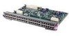
... 3.0-1.5 AMPS Power On/off switch Table 2-3 Slot No. 1 2 3 Unit Numbering Addresses for Dual Serial and Two Ethernet Modules Interface Type Serial Port (Top) Serial Port (Bottom) Ethernet Ethernet Unit Address No. 1 0 0 1 Figure 2-3 shows a chassis configured with fewer than three network processor modules, you must... place a slot filler panel in the open slot to Make Connections If the Token Ring module in Figure 2-2 was replaced by a second Ethernet module, the unit addresses would be as listed in Table 2-2. H1402 a 2-8 Cisco 4000 Series ...
... 3.0-1.5 AMPS Power On/off switch Table 2-3 Slot No. 1 2 3 Unit Numbering Addresses for Dual Serial and Two Ethernet Modules Interface Type Serial Port (Top) Serial Port (Bottom) Ethernet Ethernet Unit Address No. 1 0 0 1 Figure 2-3 shows a chassis configured with fewer than three network processor modules, you must... place a slot filler panel in the open slot to Make Connections If the Token Ring module in Figure 2-2 was replaced by a second Ethernet module, the unit addresses would be as listed in Table 2-2. H1402 a 2-8 Cisco 4000 Series ...

Hardware Maintenance Manual
Page 84
...network activity on the far right indicates that the system card's power is working. Ethernet Network Processor Module LED Indicators When facing the rear of the chassis, the LEDs on the dual-port Ethernet network processor module are labeled as shown in Figure 4-3. (Also see Figure ... you have a link. 4-4 Cisco 4000 Series Hardware Installation and Maintenance The other LEDs on the single-port Ethernet network processor module are labeled as shown in Figure 4-2. (Also see Figure 2-5.) Figure 4-3 Single-Port Ethernet Network Processor Module LEDs H1126a AUI POL LNK RX...
...network activity on the far right indicates that the system card's power is working. Ethernet Network Processor Module LED Indicators When facing the rear of the chassis, the LEDs on the dual-port Ethernet network processor module are labeled as shown in Figure 4-3. (Also see Figure ... you have a link. 4-4 Cisco 4000 Series Hardware Installation and Maintenance The other LEDs on the single-port Ethernet network processor module are labeled as shown in Figure 4-2. (Also see Figure 2-5.) Figure 4-3 Single-Port Ethernet Network Processor Module LEDs H1126a AUI POL LNK RX...

Hardware Maintenance Manual
Page 133
Other usage will invalidate any approval given to meet the requirements of Power Supply. Connection of NET1 and NET2. The Cisco 4000 router is made. The ports marked "Ethernet," "10BaseT," "Token Ring," "Console," and "AUX" have previously been evaluated against British Telecommunications plc (Post Office) Technical Guides 2 or 26 and given permission to attach...
Other usage will invalidate any approval given to meet the requirements of Power Supply. Connection of NET1 and NET2. The Cisco 4000 router is made. The ports marked "Ethernet," "10BaseT," "Token Ring," "Console," and "AUX" have previously been evaluated against British Telecommunications plc (Post Office) Technical Guides 2 or 26 and given permission to attach...
Hardware Maintenance Manual
Page 138
... B-1-B-6 boot field B-3 changing settings B-2 Cisco 4500-M D-4 Cisco 4700 D-4 displaying settings C-3 resetting C-3 confreg command D-4 connections 10BaseT 2-10 9-pin D-type 3-2 auxiliary port 2-9 considerations when making 2-10 console port 2-9 Ethernet attaching to network 3-3 port, considerations 2-12 final 3-22 NT1 3-6 optical bypass switch 3-13 power 3-22 preparing to make 2-7 serial 3-5...on serial interface port 2-21 connection to DTE port 2-9 CT1 cables 2-31, A-22 network processor module 2-30 D danger, warnings description xvii 4 Cisco 4000 Series Hardware Installation and Maintenance
... B-1-B-6 boot field B-3 changing settings B-2 Cisco 4500-M D-4 Cisco 4700 D-4 displaying settings C-3 resetting C-3 confreg command D-4 connections 10BaseT 2-10 9-pin D-type 3-2 auxiliary port 2-9 considerations when making 2-10 console port 2-9 Ethernet attaching to network 3-3 port, considerations 2-12 final 3-22 NT1 3-6 optical bypass switch 3-13 power 3-22 preparing to make 2-7 serial 3-5...on serial interface port 2-21 connection to DTE port 2-9 CT1 cables 2-31, A-22 network processor module 2-30 D danger, warnings description xvii 4 Cisco 4000 Series Hardware Installation and Maintenance

Hardware Maintenance Manual
Page 141
... network activity indicator 4-4 connection considerations network processor module ATM 2-34 network processor modules dual serial 2-20 Ethernet 2-10 FDDI 2-27, 4-10 LED indicators ...the chassis 5-1 operating conditions European Community F-1 temperature 1-3 operating conditions United Kingdom E-1 optical bypass switch connecting to 3-13 uses 2-28 ordering publications xv overview, series 1-1 P packing list 2-...X.21 dual-port A-14 four-port A-15 polarity, Ethernet LED 4-5 port locations 2-7 software configuration, serial 4-8 power LED indication 3-22 light 4-3 specifications 1-3 supply features ...
... network activity indicator 4-4 connection considerations network processor module ATM 2-34 network processor modules dual serial 2-20 Ethernet 2-10 FDDI 2-27, 4-10 LED indicators ...the chassis 5-1 operating conditions European Community F-1 temperature 1-3 operating conditions United Kingdom E-1 optical bypass switch connecting to 3-13 uses 2-28 ordering publications xv overview, series 1-1 P packing list 2-...X.21 dual-port A-14 four-port A-15 polarity, Ethernet LED 4-5 port locations 2-7 software configuration, serial 4-8 power LED indication 3-22 light 4-3 specifications 1-3 supply features ...
Hardware Maintenance Manual
Page 143
... Token Ring connecting 3-2 connecting cable 3-2 connections 2-13 LED indications 4-5 port, location 2-7 tools required for installation 2-6 transceiver cable 2-11 transmit, Ethernet LED 4-5 tray, component, replacing 5-20 troubleshooting cables 4-2 initial hardware configuration 4-1 network processor modules 4-2 power and cooling systems 4-2 U unit numbering 2-7 United Kingdom operating condition warnings E-1 UniverCD xv V V.35 cable pinouts dual-port A-10 four...
... Token Ring connecting 3-2 connecting cable 3-2 connections 2-13 LED indications 4-5 port, location 2-7 tools required for installation 2-6 transceiver cable 2-11 transmit, Ethernet LED 4-5 tray, component, replacing 5-20 troubleshooting cables 4-2 initial hardware configuration 4-1 network processor modules 4-2 power and cooling systems 4-2 U unit numbering 2-7 United Kingdom operating condition warnings E-1 UniverCD xv V V.35 cable pinouts dual-port A-10 four...
