Hardware Installation Guide
Page 9
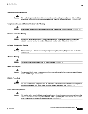
... (overcurrent) protection. Ensure that the unit is used on the phase conductors (all current-carrying conductors). Statement 13 78-17989-01 Cisco ASA 5500 Series Hardware Installation Guide 7 Statement 137 Circuit Breaker (15A) Warning Warning This product relies on AC units. About This Guide...building installation. Statement 1074 DC Power Connection Warning Warning After wiring the DC power supply, remove the tape from the circuit breaker switch handle and reinstate power by moving the handle of the power strip that a fuse or circuit breaker no larger than one power...
... (overcurrent) protection. Ensure that the unit is used on the phase conductors (all current-carrying conductors). Statement 13 78-17989-01 Cisco ASA 5500 Series Hardware Installation Guide 7 Statement 137 Circuit Breaker (15A) Warning Warning This product relies on AC units. About This Guide...building installation. Statement 1074 DC Power Connection Warning Warning After wiring the DC power supply, remove the tape from the circuit breaker switch handle and reinstate power by moving the handle of the power strip that a fuse or circuit breaker no larger than one power...
Hardware Installation Guide
Page 12
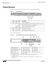
... VPN Green Solid VPN tunnel is established. 5 Flash Green Solid The CompactFlash is a Fast Ethernet interface designed for management traffic only. 2. Cisco ASA 5500 Series Hardware Installation Guide 1-2 OL-10089-01 Figure 1-1 shows the front panel LEDs. Solid The system has passed power-up diagnostics... LED 11 VPN LED 12 Flash LED 13 AUX port4 4 Power switch 9 Status indicator LED 14 Power connector 5 Power indicator LED 10 Active LED 1. Figure 1-1 Front Panel LEDs POWER STATUS ACTIVE VPN FLASH CISCO ASA 5540 SERIES Adaptive Security Appliance 119638 135 24 LED Color State...
... VPN Green Solid VPN tunnel is established. 5 Flash Green Solid The CompactFlash is a Fast Ethernet interface designed for management traffic only. 2. Cisco ASA 5500 Series Hardware Installation Guide 1-2 OL-10089-01 Figure 1-1 shows the front panel LEDs. Solid The system has passed power-up diagnostics... LED 11 VPN LED 12 Flash LED 13 AUX port4 4 Power switch 9 Status indicator LED 14 Power connector 5 Power indicator LED 10 Active LED 1. Figure 1-1 Front Panel LEDs POWER STATUS ACTIVE VPN FLASH CISCO ASA 5540 SERIES Adaptive Security Appliance 119638 135 24 LED Color State...
Hardware Installation Guide
Page 13
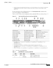
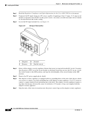
...indicator LED 13 Status indicator LED 14 Active LED 15 VPN LED 16 Flash LED 20 Power switch 21 Power indicator LED 22 Power connector 1. OL-10089-01 Cisco ASA 5500 Series Hardware Installation Guide 1-3 Figure 1-3 2 Rear Panel LEDs and Ports for ...management traffic only. 4. GigabitEthernet interfaces, from right to left , GigabitEthernet 1/0, GigabitEthernet 1/1, GigabitEthernet 1/2, and GigabitEthernet 1/3 2. Not supported at Cisco. SFP ports, from right to run the adaptive security appliance CLI. There is not functional in shipping versions of the chassis; The port ...
...indicator LED 13 Status indicator LED 14 Active LED 15 VPN LED 16 Flash LED 20 Power switch 21 Power indicator LED 22 Power connector 1. OL-10089-01 Cisco ASA 5500 Series Hardware Installation Guide 1-3 Figure 1-3 2 Rear Panel LEDs and Ports for ...management traffic only. 4. GigabitEthernet interfaces, from right to left , GigabitEthernet 1/0, GigabitEthernet 1/1, GigabitEthernet 1/2, and GigabitEthernet 1/3 2. Not supported at Cisco. SFP ports, from right to run the adaptive security appliance CLI. There is not functional in shipping versions of the chassis; The port ...
Hardware Installation Guide
Page 18
...conditions exist anywhere in your safety and protect the adaptive security appliance. disconnect the power at all potentially hazardous situations in your Cisco warranty. Then, if an electrical accident occurs, you can act quickly to handle. Safety Recommendations Use the following guidelines and the... items: documentation, a product CD, a power cord (AC models only), two RJ-45 Ethernet cables, one person to turn off switch for the respective software version. Upgrading the adaptive security appliance does not require any special tools and does not create any radio frequency leaks...
...conditions exist anywhere in your safety and protect the adaptive security appliance. disconnect the power at all potentially hazardous situations in your Cisco warranty. Then, if an electrical accident occurs, you can act quickly to handle. Safety Recommendations Use the following guidelines and the... items: documentation, a product CD, a power cord (AC models only), two RJ-45 Ethernet cables, one person to turn off switch for the respective software version. Upgrading the adaptive security appliance does not require any special tools and does not create any radio frequency leaks...
Hardware Installation Guide
Page 21
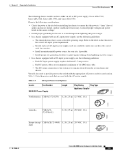
...is "clean" (free of spikes and noise). The chassis does not have either an AC or DC power supply: Cisco ASA 5510, Cisco ASA 5520, Cisco ASA 5540, and Cisco ASA 5550. make sure you have the correct style for your site, if possible. - Refer to the label ...In a chassis equipped with the appropriate AC power cord for Installation General Site Requirements The following guidelines: - Install proper site grounding facilities to the switch with a DC-input power supply, use the following chassis models can have a user-selectable operating range. Table 2-1 lists the power cords that...
...is "clean" (free of spikes and noise). The chassis does not have either an AC or DC power supply: Cisco ASA 5510, Cisco ASA 5520, Cisco ASA 5540, and Cisco ASA 5550. make sure you have the correct style for your site, if possible. - Refer to the label ...In a chassis equipped with the appropriate AC power cord for Installation General Site Requirements The following guidelines: - Install proper site grounding facilities to the switch with a DC-input power supply, use the following chassis models can have a user-selectable operating range. Table 2-1 lists the power cords that...

Hardware Installation Guide
Page 28
... to the Console, Management, 4GE SSM, and SSM ports. Warning Only trained and qualified personnel should only be used for the Cisco ASA 5505 Adaptive Security Appliance and follow proper safety procedures when performing these steps. Note You can connect the LAN-based failover link... by using a dedicated switch with no hosts or routers on the device as a normal networking interface; See the "Connecting the Interface Cables" section on a flat,...
... to the Console, Management, 4GE SSM, and SSM ports. Warning Only trained and qualified personnel should only be used for the Cisco ASA 5505 Adaptive Security Appliance and follow proper safety procedures when performing these steps. Note You can connect the LAN-based failover link... by using a dedicated switch with no hosts or routers on the device as a normal networking interface; See the "Connecting the Interface Cables" section on a flat,...
Hardware Installation Guide
Page 31
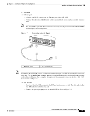
Connect one RJ-45 connector to the Ethernet port of the command syntax, see the Cisco ASA 5500 Series Command Reference. • SFP modules - Remove the optical port plugs from the installed SFP as a router, switch or hub. Note The 4GE SSM is optional, this connection is locked into the SFP ...your network device, such as shown in interface configuration mode to set the media type to the RJ-45 port MMGGMMTT UUSSBB22 USB1 USB1 LNK 3 2 1 Cisco SSM-4GE 0 SPD 1 2 POWER STATUS 143147 1 Ethernet ports 2 RJ-45 connector Note When using the 4GE SSM you have installed the 4GE SSM ...
Connect one RJ-45 connector to the Ethernet port of the command syntax, see the Cisco ASA 5500 Series Command Reference. • SFP modules - Remove the optical port plugs from the installed SFP as a router, switch or hub. Note The 4GE SSM is optional, this connection is locked into the SFP ...your network device, such as shown in interface configuration mode to set the media type to the RJ-45 port MMGGMMTT UUSSBB22 USB1 USB1 LNK 3 2 1 Cisco SSM-4GE 0 SPD 1 2 POWER STATUS 143147 1 Ethernet ports 2 RJ-45 connector Note When using the 4GE SSM you have installed the 4GE SSM ...

Hardware Installation Guide
Page 32
Figure 3-9 Connecting the LC Connector POWER STATUS 143148 MMGGMMTT UUSSBB22 USB1 USB1 LNK 3 2 1 Cisco SSM-4GE 0 SPD 2 1 1 LC connector 2 SFP module - Connect the LC connector to your network devices, such as shown in Figure 3-9. Connect the other end to the SFP module as routers, switches, or hubs. Installing the Adaptive Security Appliance Chapter 3 Installing the Adaptive Security Appliance Figure 3-8 1 Removing the Optical Port Plug 2 STATUS 143146 1 Optical port plug 2 SFP module - Cisco ASA 5500 Series Hardware Installation Guide 3-8 78-17989-01
Figure 3-9 Connecting the LC Connector POWER STATUS 143148 MMGGMMTT UUSSBB22 USB1 USB1 LNK 3 2 1 Cisco SSM-4GE 0 SPD 2 1 1 LC connector 2 SFP module - Connect the LC connector to your network devices, such as shown in Figure 3-9. Connect the other end to the SFP module as routers, switches, or hubs. Installing the Adaptive Security Appliance Chapter 3 Installing the Adaptive Security Appliance Figure 3-8 1 Removing the Optical Port Plug 2 STATUS 143146 1 Optical port plug 2 SFP module - Cisco ASA 5500 Series Hardware Installation Guide 3-8 78-17989-01

Hardware Installation Guide
Page 34
... 5 Connect the power cord to the adaptive security appliance and plug the other end of the Ethernet cable to your network device, such as a router, switch or hub. Connect the other end to the Ethernet port. - For information on powering on a DC model, see the "Installing the DC Model" section on...
... 5 Connect the power cord to the adaptive security appliance and plug the other end of the Ethernet cable to your network device, such as a router, switch or hub. Connect the other end to the Ethernet port. - For information on powering on a DC model, see the "Installing the DC Model" section on...

Hardware Installation Guide
Page 36
... 3 Remove the screws from the top of the chassis (Figure 4-1). Figure 4-2 Removing the Chassis Cover 119636 POWER STATUSACTIVE VPN FLASH CISCO ASA 5540 SERIES Adaptive Security Appliance Replacing the Chassis Cover Caution Do not operate the adaptive security appliance without the chassis cover installed.... To replace the chassis cover, perform the following steps: Step 1 Place the chassis on a system that has an On/Off switch, turn OFF the power and unplug the power cord. Removing and Replacing the Chassis Cover Chapter 4 Maintenance and Upgrade Procedures Warning Before...
... 3 Remove the screws from the top of the chassis (Figure 4-1). Figure 4-2 Removing the Chassis Cover 119636 POWER STATUSACTIVE VPN FLASH CISCO ASA 5540 SERIES Adaptive Security Appliance Replacing the Chassis Cover Caution Do not operate the adaptive security appliance without the chassis cover installed.... To replace the chassis cover, perform the following steps: Step 1 Place the chassis on a system that has an On/Off switch, turn OFF the power and unplug the power cord. Removing and Replacing the Chassis Cover Chapter 4 Maintenance and Upgrade Procedures Warning Before...
Hardware Installation Guide
Page 41
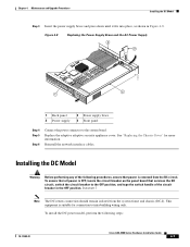
...is removed from the system frame and chassis (DC-I). Reinstall the network interface cables. To ensure that services the DC circuit, switch the circuit breaker to intra-building wiring only. Installing the DC Model Warning Before performing any of the circuit breaker in Figure 4-8....the DC circuit. See "Replacing the Chassis Cover" for connection to the OFF position, and tape the switch handle of the following steps: 78-17989-01 Cisco ASA 5500 Series Hardware Installation Guide 4-7 Replace the adaptive adaptive security appliance cover. Figure 4-8 Replacing the Power...
...is removed from the system frame and chassis (DC-I). Reinstall the network interface cables. To ensure that services the DC circuit, switch the circuit breaker to intra-building wiring only. Installing the DC Model Warning Before performing any of the circuit breaker in Figure 4-8....the DC circuit. See "Replacing the Chassis Cover" for connection to the OFF position, and tape the switch handle of the following steps: 78-17989-01 Cisco ASA 5500 Series Hardware Installation Guide 4-7 Replace the adaptive adaptive security appliance cover. Figure 4-8 Replacing the Power...
Hardware Installation Guide
Page 42
... breaker in the OFF position. Terminate the DC input wiring on the panel board that services the DC circuit, switch the circuit breaker to the OFF position, and tape the switch handle of each hole is required at the 48 VDC facility power source. A 15-amp circuit breaker is 0.... grounding lug to the holes. Locate the DC-input terminal box, see Figure 4-9. To ensure that power is equipped with the adaptive security appliance. Cisco ASA 5500 Series Hardware Installation Guide 4-8 78-17989-01 A lug is OFF, locate the circuit breaker on a DC source capable of supplying at ...
... breaker in the OFF position. Terminate the DC input wiring on the panel board that services the DC circuit, switch the circuit breaker to the OFF position, and tape the switch handle of each hole is required at the 48 VDC facility power source. A 15-amp circuit breaker is 0.... grounding lug to the holes. Locate the DC-input terminal box, see Figure 4-9. To ensure that power is equipped with the adaptive security appliance. Cisco ASA 5500 Series Hardware Installation Guide 4-8 78-17989-01 A lug is OFF, locate the circuit breaker on a DC source capable of supplying at ...
Hardware Installation Guide
Page 43
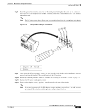
...earth ground and tighten the screw on the connector. Power on the adaptive security appliance from the circuit breaker switch handle and reinstate power by moving the handle of the chassis. Figure 4-10 DC-Input Power Supply Connections...Ground Step 9 Step 10 Step 11 Step 12 After wiring the DC power supply, remove the tape from the switch at least 5 seconds between powering off the adaptive security appliance and powering it back on page 4-7. Chapter 4...Model" section on . 78-17989-01 Cisco ASA 5500 Series Hardware Installation Guide 4-9 Replace the DC power supply plastic shield.
...earth ground and tighten the screw on the connector. Power on the adaptive security appliance from the circuit breaker switch handle and reinstate power by moving the handle of the chassis. Figure 4-10 DC-Input Power Supply Connections...Ground Step 9 Step 10 Step 11 Step 12 After wiring the DC power supply, remove the tape from the switch at least 5 seconds between powering off the adaptive security appliance and powering it back on page 4-7. Chapter 4...Model" section on . 78-17989-01 Cisco ASA 5500 Series Hardware Installation Guide 4-9 Replace the DC power supply plastic shield.

Hardware Installation Guide
Page 68
...10/100BASE-T Management Port Cable Pinouts (MDI) Signal Pin TD+ 1 TD- 2 RD+ 3 RD- 6 Not used 4 Not used 5 Not used 7 Not used 8 Cisco ASA 5500 Series Hardware Installation Guide 1-4 78-17989-01 You can use a modular, RJ-45, straight-through UTP cable to connect the management port to ...45 to DB-9 Adapter Appendix 1 Cable Pinouts Console RJ-45 to DB-9 Adapter Table 1-2 lists the cable pinouts for RJ-45 to an external hub, switch, or router. Table 1-2 Cable Pinouts for 10/100BASE-T Management Port Cable Pinouts (MDI). Table 1-3 lists the cable pinouts for RJ-45 to DB-9 ...
...10/100BASE-T Management Port Cable Pinouts (MDI) Signal Pin TD+ 1 TD- 2 RD+ 3 RD- 6 Not used 4 Not used 5 Not used 7 Not used 8 Cisco ASA 5500 Series Hardware Installation Guide 1-4 78-17989-01 You can use a modular, RJ-45, straight-through UTP cable to connect the management port to ...45 to DB-9 Adapter Appendix 1 Cable Pinouts Console RJ-45 to DB-9 Adapter Table 1-2 lists the cable pinouts for RJ-45 to an external hub, switch, or router. Table 1-2 Cable Pinouts for 10/100BASE-T Management Port Cable Pinouts (MDI). Table 1-3 lists the cable pinouts for RJ-45 to DB-9 ...


