Cisco WS-C5509 Support and Manuals
Get Help and Manuals for this Cisco item
View All Support Options Below
Free Cisco WS-C5509 manuals!
Problems with Cisco WS-C5509?
Ask a Question
Free Cisco WS-C5509 manuals!
Problems with Cisco WS-C5509?
Ask a Question
Popular Cisco WS-C5509 Manual Pages
Hardware Installation Guide - Page 3
...2-4 Power Supply Considerations 2-4 Configuring Equipment Racks 2-6
Installing the Adaptive Security Appliance 3-1 Installing the Adaptive Security Appliance 3-1 Rack-Mounting the Chassis 3-2 Setting the Chassis on a Desktop 3-3 Connecting the Interface Cables 3-4
Maintenance and Upgrade Procedures 4-1 Removing and Replacing the Chassis Cover 4-1
Cisco ASA 5500 Series Hardware Installation Guide
1
Hardware Installation Guide - Page 4
... in the SSM 4-4 Removing and Replacing the Power Supply 4-4 Removing the AC Power Supply 4-4 Replacing the AC Power Supply 4-6 Installing the DC Model 4-7 Removing and Replacing the CompactFlash 4-10 Removing the System CompactFlash 4-10 Replacing the System CompactFlash 4-11 Removing the User CompactFlash 4-12 Replacing the User CompactFlash 4-12 Installing and Replacing the 4GE SSM 4-13 Overview...
Hardware Installation Guide - Page 6
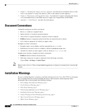
...covered in the manual. Installation Warnings
Be sure to enter in boldface screen font. • Variables for which you must supply a value are entered literally as shown. • Italics indicate arguments for Rack-Mounting and Servicing, page 6 • Short-Circuit Protection Warning, page 6 • SELV Circuit Warning, page 6
Cisco ASA 5500 Series Hardware Installation Guide
4
78-17989...
Hardware Installation Guide - Page 7

... Panel Requirement, page 8
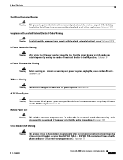
Power Supply Disconnection Warning
Warning Before working on a chassis or working on AC units; Statement 43
Wrist Strap Warning
Warning During this procedure, wear grounding wrist straps to avoid ESD damage to the terminals. Statement 1004
78-17989-01
Cisco ASA 5500 Series Hardware Installation Guide
5 About This Guide
• Ground Conductor Warning...
Hardware Installation Guide - Page 9
... shock when servicing a unit, disconnect the power cord of the building installation. Statement 8
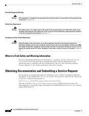
AC Power Disconnection Warning
Warning Before working on a chassis or working near power supplies, unplug the power cord on the building's installation for short-circuit (overcurrent) protection. Statement 13
78-17989-01
Cisco ASA 5500 Series Hardware Installation Guide
7 Ensure that...
Hardware Installation Guide - Page 10
...service. Operating the unit without the safety cover installed. Statement 142
Where to be grounded. Obtaining Documentation and Submitting a Service Request
For information on obtaining documentation, submitting a service... the chassis. Cisco currently supports RSS Version 2.0. About This Guide
Grounded Equipment Warning
Warning This equipment is an integral part of the product...
Hardware Installation Guide - Page 12
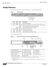
.... Figure 1-2 shows the rear panel. Cisco ASA 5500 Series Hardware Installation Guide
1-2
OL-10089-01 Solid The system has passed power-up diagnostics have failed.
3 Active Green Flashing There is network activity.
4 VPN Green Solid VPN tunnel is established.
5 Flash Green Solid The CompactFlash is being accessed.
Not supported at this time. 3. Product Overview
Chapter...
Hardware Installation Guide - Page 14
...Cisco ASA 5550
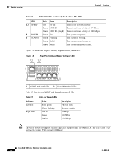
LED 3, 8 SPEED
4 POWER 5 STATUS
Color State Off 10 MB Green 100 MB Amber 1000 MB (GigE) Green On Green Flashing Green Solid Amber Solid
Description There is booting.
The system is no network activity. Cisco ASA 5500 Series Hardware Installation Guide... and Network interface LEDs. The Cisco ASA 5520 and the Cisco ASA 5540 support 1000BaseT. Figure 1-4 shows the adaptive...
Hardware Installation Guide - Page 21
..., if possible.
-
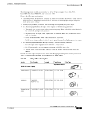
Refer to the switch with an AC-input power supply, use the following chassis models can have either an AC or DC power supply: Cisco ASA 5510, Cisco ASA 5520, Cisco ASA 5540, and Cisco ASA 5550. Install an uninterruptible power source for the correct AC-input power requirement.
-
Table 2-1 lists the power cords that the power is to guard against damage from...
Hardware Installation Guide - Page 40

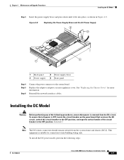
... out as shown in Figure 4-7. Lift the rear of the adaptive adaptive security appliance.
Cisco ASA 5500 Series Hardware Installation Guide
4-6
78-17989-01
Replacing the AC Power Supply
To replace the AC power supply, perform the following steps:
Step 1 Step 2
Insert the new power supply into place and slide it towards the back of the adaptive adaptive security appliance from...
Hardware Installation Guide - Page 41
...only.
Figure 4-8
Replacing the Power Supply Brace and the AC Power Supply
4 3
119579
2 1
1 Back panel 2 Power supply
3 Power supply brace 4 Front panel
Step 4 Step 5
Step 6
Connect the power connector to the OFF position, and tape the switch handle of the following steps:
78-17989-01
Cisco ASA 5500 Series Hardware Installation Guide
4-7 To install the DC power model, perform the...
Hardware Installation Guide - Page 42
... DC circuit. Cisco ASA 5500 Series Hardware Installation Guide
4-8
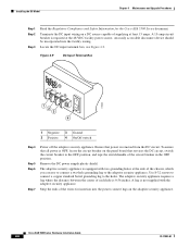
78-17989-01 Terminate the DC input wiring on a DC source capable of the circuit breaker in the OFF position. Figure 4-9
DC-Input Terminal Box
+ -
119640
1 2 3
4
1 Negative 3 Ground 2 Positive 4 On/Off switch
Step 4 Step 5 Step 6
Step 7
Power off the adaptive security appliance. Ensure that services the DC...
Hardware Installation Guide - Page 43
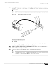
... appliance, wait at the rear of the circuit breaker to remain isolated from the switch at least 5 seconds between powering off the adaptive security appliance and powering it back on page 4-7. See Figure 4-10, and using the same method as described in "Installing the DC Model" section on .
78-17989-01
Cisco ASA 5500 Series Hardware Installation Guide
4-9
Hardware Installation Guide - Page 71
Numerics
1000 W power supplies power cords (table) 2-5
4GE SSM 4-15, 4-22
A
AC-input power cords product numbers (table) 2-5
ASA replacing lithium battery 4-4
AUX port 1-2
C
chassis covers removing 4-1 replacing 4-2
circuit breaker for DC unit 2-3 Cisco warranty 2-2 CompactFlash
External 1-2, 1-3 Internal 4-10, 4-12 Console port 3-6 CPU 1-5
E
electrostatic discharge see ESD
equipment racks tips ...
Hardware Installation Guide - Page 72
... power supplies
considerations 2-4 product overview 1-2
R
rear panels (figure) 1-4 RJ-45 connector
pinouts 1-4 RJ-45 port 3-7 rubber feet
attaching 3-3
S
safety 2-2 Serial Console port 1-2, 1-3 SFP 3-7, 4-16 site environment 2-4 SSM 3-9, 4-4
4GE SSM connecting 3-7 installing 4-15, 4-22 LEDs 1-3, 4-14 replacing 4-16, 4-23
V
ventilation fans 2-7
IN-2
Cisco ASA 5500 Series Hardware Installation...
Cisco WS-C5509 Reviews
We have not received any reviews for Cisco yet.