
Installation Guide
Page 5
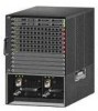
...pin mini Type B can be active at a time. Figure 2 12 Back Panel 251198 3 4 1 Power supply PS1 2 Power supply PS1 on/off switch 3 Power supply PS1 AC cable connection 5 4 Power supply PS2 slot with blank cover 5 Fan tray Checking the Controller LEDs If your controller is plugged...USB console port the RJ-45 port becomes inactive. Note An amber LED could indicate an error or a possible hardware failure. 78-18998-01 Cisco 5500 Series Wireless Controller Installation Guide 5 The LED indicators are not compatible. Note Four-pin mini Type B connectors are easily confused with a power...
...pin mini Type B can be active at a time. Figure 2 12 Back Panel 251198 3 4 1 Power supply PS1 2 Power supply PS1 on/off switch 3 Power supply PS1 AC cable connection 5 4 Power supply PS2 slot with blank cover 5 Fan tray Checking the Controller LEDs If your controller is plugged...USB console port the RJ-45 port becomes inactive. Note An amber LED could indicate an error or a possible hardware failure. 78-18998-01 Cisco 5500 Series Wireless Controller Installation Guide 5 The LED indicators are not compatible. Note Four-pin mini Type B connectors are easily confused with a power...
Installation Guide
Page 6
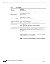
...Present with failure. When this LED is on, the RJ-45 console port LED is off . Note Verify that the power cord in failure condition. Cisco 5500 Series Wireless Controller Installation Guide 6 78-18998-01 Green: Present and enabled. Amber: Present with failure. Green: Indicates SFP port is active and link ...down. Blinks amber: Indicates that the standby power supply fan is not spinning or that a power supply is in installed correctly and that the power switch is on , the USB console port LED is off . Note When the PS1 or PS2 LED is over temperature. Green: Indicates RP/SP ...
...Present with failure. When this LED is on, the RJ-45 console port LED is off . Note Verify that the power cord in failure condition. Cisco 5500 Series Wireless Controller Installation Guide 6 78-18998-01 Green: Present and enabled. Amber: Present with failure. Green: Indicates SFP port is active and link ...down. Blinks amber: Indicates that the standby power supply fan is not spinning or that a power supply is in installed correctly and that the power switch is on , the USB console port LED is off . Note When the PS1 or PS2 LED is over temperature. Green: Indicates RP/SP ...
Installation Guide
Page 9
.... Yes is less convenient, but has lower security (session can be on the proximity of the switch to proper grounding facilities • Crimping tool large enough to local and national installation requirements; No is... Installing the Controller The following additional items (not found in the accessory kit) are required to ground the chassis: • Grounding cable (6 AWG recommended), sized according to accommodate girth of lug • Wire-stripping... radio resource management (RRM) (enabled or disabled). 78-18998-01 Cisco 5500 Series Wireless Controller Installation Guide 9
.... Yes is less convenient, but has lower security (session can be on the proximity of the switch to proper grounding facilities • Crimping tool large enough to local and national installation requirements; No is... Installing the Controller The following additional items (not found in the accessory kit) are required to ground the chassis: • Grounding cable (6 AWG recommended), sized according to accommodate girth of lug • Wire-stripping... radio resource management (RRM) (enabled or disabled). 78-18998-01 Cisco 5500 Series Wireless Controller Installation Guide 9

Installation Guide
Page 16
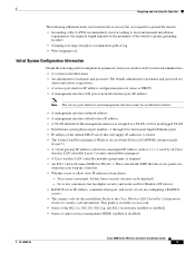
...that you attach the cable guide to prevent the cables from obscuring the front panel of the switch and the other devices installed in a 2-post equipment rack: Step 1 Attach one power supply... 11). Statement 1028 Follow these steps to flush mount the controller in the rack. Cisco 5500 Series Wireless Controller Installation Guide 16 78-18998-01 Figure 11 Installing the Cable Guide RP SP USB0 USB1... CONSOLE EN EN Cisco 5500 Series Wireless Controller 12 34 56 78 Model 5508 PS1 PS2 SYS ACT 251240 Installing the ...
...that you attach the cable guide to prevent the cables from obscuring the front panel of the switch and the other devices installed in a 2-post equipment rack: Step 1 Attach one power supply... 11). Statement 1028 Follow these steps to flush mount the controller in the rack. Cisco 5500 Series Wireless Controller Installation Guide 16 78-18998-01 Figure 11 Installing the Cable Guide RP SP USB0 USB1... CONSOLE EN EN Cisco 5500 Series Wireless Controller 12 34 56 78 Model 5508 PS1 PS2 SYS ACT 251240 Installing the ...
Installation Guide
Page 17
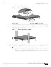
...ACT 12 251200 1 Front bracket 2 M4x0.7 x 8mm flat head screws Step 2 Mount the front of the switch and the other devices installed in the Rack RP SP USB0 USB1 CONSOLE EN EN Cisco 5500 Series Wireless Controller 12 34 56 78 Model 5508 PS1 PS2 SYS ACT 274464 Step 3 (Optional) Use the... supplied M4x0.7 x 20mm pan head screw to attach the cable guide to prevent the cables from obscuring the front panel of the controller chassis into the rack ...
...ACT 12 251200 1 Front bracket 2 M4x0.7 x 8mm flat head screws Step 2 Mount the front of the switch and the other devices installed in the Rack RP SP USB0 USB1 CONSOLE EN EN Cisco 5500 Series Wireless Controller 12 34 56 78 Model 5508 PS1 PS2 SYS ACT 274464 Step 3 (Optional) Use the... supplied M4x0.7 x 20mm pan head screw to attach the cable guide to prevent the cables from obscuring the front panel of the controller chassis into the rack ...
Installation Guide
Page 25
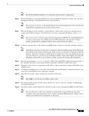
... Step 12 Step 13 Step 14 Enter the network name, or service set to assign their radios. Enter yes to allow clients to match the switch interface configuration. The group dynamically elects a leader to automatically form an RF group with the same virtual interface IP address. Step 9 Enter the IP address... enables the controller to optimize RRM parameter settings, such as guest web authentication and VPN termination. Enter the code for the group. 78-18998-01 Cisco 5500 Series Wireless Controller Installation Guide 25
... Step 12 Step 13 Step 14 Enter the network name, or service set to assign their radios. Enter yes to allow clients to match the switch interface configuration. The group dynamically elects a leader to automatically form an RF group with the same virtual interface IP address. Step 9 Enter the IP address... enables the controller to optimize RRM parameter settings, such as guest web authentication and VPN termination. Enter the code for the group. 78-18998-01 Cisco 5500 Series Wireless Controller Installation Guide 25
Installation Guide
Page 28
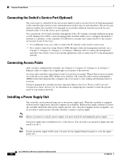
...power from a PC running a terminal emulation program or a PC running Cisco WCS, a network management tool that enables you to configure and monitor a network of -band controller management from the controller to the switch's service port in slot 2. Connecting Access Points After you must first... should the other power supply unit fail. Note Before you remove or install a power supply, you must switch off and unplug the power supply. Cisco 5500 Series Wireless Controller Installation Guide 28 78-18998-01 However, you have prepared the controller for basic operation. ...
...power from a PC running a terminal emulation program or a PC running Cisco WCS, a network management tool that enables you to configure and monitor a network of -band controller management from the controller to the switch's service port in slot 2. Connecting Access Points After you must first... should the other power supply unit fail. Note Before you remove or install a power supply, you must switch off and unplug the power supply. Cisco 5500 Series Wireless Controller Installation Guide 28 78-18998-01 However, you have prepared the controller for basic operation. ...


