
Installation Guide
Page 5
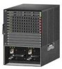
... used. Note An amber LED could indicate an error or a possible hardware failure. 78-18998-01 Cisco 5500 Series Wireless Controller Installation Guide 5 Controller Overview With the Cisco Windows USB Console Driver, you can plug and unplugg the USB cable from the USB port, the RJ... Figure 2 12 Back Panel 251198 3 4 1 Power supply PS1 2 Power supply PS1 on/off switch 3 Power supply PS1 AC cable connection 5 4 Power supply PS2 slot with blank cover 5 Fan tray Checking the Controller LEDs If your controller is removed from the console port without affecting Windows HyperTerminal ...
... used. Note An amber LED could indicate an error or a possible hardware failure. 78-18998-01 Cisco 5500 Series Wireless Controller Installation Guide 5 Controller Overview With the Cisco Windows USB Console Driver, you can plug and unplugg the USB cable from the USB port, the RJ... Figure 2 12 Back Panel 251198 3 4 1 Power supply PS1 2 Power supply PS1 on/off switch 3 Power supply PS1 AC cable connection 5 4 Power supply PS2 slot with blank cover 5 Fan tray Checking the Controller LEDs If your controller is removed from the console port without affecting Windows HyperTerminal ...
Installation Guide
Page 6
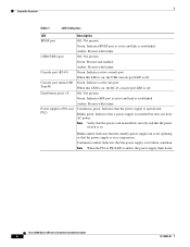
... the RJ-45 console port LED is on. Amber: Present with failure. Blinks green: Indicates that the power switch is off . Note Verify that the power cord in failure condition. Cisco 5500 Series Wireless Controller Installation Guide 6 78-18998-01 Amber: Present with failure. Green: Indicates active aux port. ...ports 1-8 Power supplies (PS1 and PS2) Description Off: Not present. Amber: Present with failure. Blinks amber: Indicates that the standby power supply fan is not spinning or that the power supply is amber, the power supply shuts down. Off: Not present.
... the RJ-45 console port LED is on. Amber: Present with failure. Blinks green: Indicates that the power switch is off . Note Verify that the power cord in failure condition. Cisco 5500 Series Wireless Controller Installation Guide 6 78-18998-01 Amber: Present with failure. Green: Indicates active aux port. ...ports 1-8 Power supplies (PS1 and PS2) Description Off: Not present. Amber: Present with failure. Blinks amber: Indicates that the standby power supply fan is not spinning or that the power supply is amber, the power supply shuts down. Off: Not present.
Installation Guide
Page 7
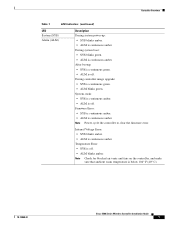
... amber. • ALM is continuous amber. During system boot: • SYS blinks green. • ALM is continuous amber. Note Check for blocked air vents and fans on the controller, and make sure that ambient room temperature is below 104° F (40° C). 78-18998-01...
... amber. • ALM is continuous amber. During system boot: • SYS blinks green. • ALM is continuous amber. Note Check for blocked air vents and fans on the controller, and make sure that ambient room temperature is below 104° F (40° C). 78-18998-01...
Installation Guide
Page 8
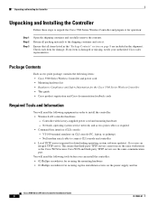
...: • Wireless LAN controller hardware - Return all items listed in the "Package Contents" section on the power supply and fan Cisco 5500 Series Wireless Controller Installation Guide 8 78-18998-01 Ensure that third-party TFTP servers cannot run on CLI console (PC, laptop...power cord • Mounting hardware kit • Regulatory Compliance and Safety Information for the Cisco 5500 Series Wireless Controller • This guide • Cisco product registration and Cisco documentation feedback cards Required Tools and Information You will need the following tools before you can ...
...: • Wireless LAN controller hardware - Return all items listed in the "Package Contents" section on the power supply and fan Cisco 5500 Series Wireless Controller Installation Guide 8 78-18998-01 Ensure that third-party TFTP servers cannot run on CLI console (PC, laptop...power cord • Mounting hardware kit • Regulatory Compliance and Safety Information for the Cisco 5500 Series Wireless Controller • This guide • Cisco product registration and Cisco documentation feedback cards Required Tools and Information You will need the following tools before you can ...

Installation Guide
Page 30
.... gently move it side to side if necessary to install the new fan assembly: Step 1 Step 2 Slide the fan assembly into the chassis until the two captive installation screws make contact with both hands and pull it from the spinning fan blades. Cisco 5500 Series Wireless Controller Installation Guide 30 78-18998-01 Caution Never operate...
.... gently move it side to side if necessary to install the new fan assembly: Step 1 Step 2 Slide the fan assembly into the chassis until the two captive installation screws make contact with both hands and pull it from the spinning fan blades. Cisco 5500 Series Wireless Controller Installation Guide 30 78-18998-01 Caution Never operate...