Installation Guide
Page 1
..., Inc., 170 West Tasman Drive, San Jose, CA 95134-1706 USA In that event, your right to radio or television communications at your Cisco 5500 Series Wireless Controller. • Compliance and Safety Information, page 1 • Controller Overview, page 3 • Unpacking and Installing the Controller, page ... interference to use the equipment may result in the equipment no longer complying with FCC requirements for Class A digital devices. Cisco 5500 Series Wireless Controller Installation Guide This guide is designed to help you may be limited by FCC regulations, and you install and ...
..., Inc., 170 West Tasman Drive, San Jose, CA 95134-1706 USA In that event, your right to radio or television communications at your Cisco 5500 Series Wireless Controller. • Compliance and Safety Information, page 1 • Controller Overview, page 3 • Unpacking and Installing the Controller, page ... interference to use the equipment may result in the equipment no longer complying with FCC requirements for Class A digital devices. Cisco 5500 Series Wireless Controller Installation Guide This guide is designed to help you may be limited by FCC regulations, and you install and ...
Installation Guide
Page 2
... 40° C), taking into account the elevated temperatures when installed in a rack or enclosed space. • When multiple Cisco 5500 Series Wireless Controllers are uncertain that apply to radio communications. Translated versions of the electrical ground before installing the controller. You are ...reasonable protection against harmful interference when the equipment is available. Statement 1024 Statement 371-Power Cable and AC Adapter Cisco 5500 Series Wireless Controller Installation Guide 2 78-18998-01 Before you are mounted in an equipment rack, be required ...
... 40° C), taking into account the elevated temperatures when installed in a rack or enclosed space. • When multiple Cisco 5500 Series Wireless Controllers are uncertain that apply to radio communications. Translated versions of the electrical ground before installing the controller. You are ...reasonable protection against harmful interference when the equipment is available. Statement 1024 Statement 371-Power Cable and AC Adapter Cisco 5500 Series Wireless Controller Installation Guide 2 78-18998-01 Before you are mounted in an equipment rack, be required ...
Installation Guide
Page 3
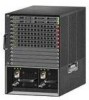
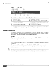
...user may arise. Figure 1 shows the front panel of service (QoS), and mobility across an entire enterprise. The Cisco 5500 Series Wireless Controller, designed for 802.11n performance and maximum scalability, supports up to provide network managers with a robust ...a domestic environment, radio disturbance may be required to an employee's residence. Controller Overview The Cisco 5500 Series Wireless Controller is used in one model: 5508. The Cisco 5500 Series Wireless Controller supports the OfficeExtend access point, which provides secure communications from a controller to an...
...user may arise. Figure 1 shows the front panel of service (QoS), and mobility across an entire enterprise. The Cisco 5500 Series Wireless Controller, designed for 802.11n performance and maximum scalability, supports up to provide network managers with a robust ...a domestic environment, radio disturbance may be required to an employee's residence. Controller Overview The Cisco 5500 Series Wireless Controller is used in one model: 5508. The Cisco 5500 Series Wireless Controller supports the OfficeExtend access point, which provides secure communications from a controller to an...
Installation Guide
Page 4
... LAN Controllers and Lightweight Access Points for Release 6.0. Only one console port (either RJ-45 or mini-USB). Cisco 5500 Series Wireless Controller Installation Guide 4 78-18998-01 See the "Connecting the Controller's Console Port" section on the USB console port. The console ... USB Console Driver must be used , this port appears as a DTE or DCE device at a time. Controller Overview Figure 1 Front Panel 12 345 6 Cisco 5500 Series Wireless Controller RP SP USB0 USB1 EN EN 7 12 3 4 56 7 8 Model 5508 PS1 PS2 SYS ALM 8 9 10 251197 1 Redundant port (RP) for ...
... LAN Controllers and Lightweight Access Points for Release 6.0. Only one console port (either RJ-45 or mini-USB). Cisco 5500 Series Wireless Controller Installation Guide 4 78-18998-01 See the "Connecting the Controller's Console Port" section on the USB console port. The console ... USB Console Driver must be used , this port appears as a DTE or DCE device at a time. Controller Overview Figure 1 Front Panel 12 345 6 Cisco 5500 Series Wireless Controller RP SP USB0 USB1 EN EN 7 12 3 4 56 7 8 Model 5508 PS1 PS2 SYS ALM 8 9 10 251197 1 Redundant port (RP) for ...

Installation Guide
Page 5
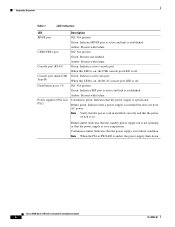
...properly, check the LEDs on /off switch 3 Power supply PS1 AC cable connection 5 4 Power supply PS2 slot with a power supply, a blank power supply cover, and a fan tray. Note An amber LED could indicate an error or a possible hardware failure. 78-18998-01 Cisco 5500 Series Wireless Controller Installation Guide 5 The ... port the RJ-45 port becomes inactive. You can use the LED indications to quickly assess the unit's status. Controller Overview With the Cisco Windows USB Console Driver, you can plug and unplugg the USB cable from the USB port, the RJ-45 port becomes active. Mac ...
...properly, check the LEDs on /off switch 3 Power supply PS1 AC cable connection 5 4 Power supply PS2 slot with a power supply, a blank power supply cover, and a fan tray. Note An amber LED could indicate an error or a possible hardware failure. 78-18998-01 Cisco 5500 Series Wireless Controller Installation Guide 5 The ... port the RJ-45 port becomes inactive. You can use the LED indications to quickly assess the unit's status. Controller Overview With the Cisco Windows USB Console Driver, you can plug and unplugg the USB cable from the USB port, the RJ-45 port becomes active. Mac ...
Installation Guide
Page 6
... LED is on. Continuous green: Indicates that the power supply is installed but does not have AC power. Blinks green: Indicates that the power switch is off . Cisco 5500 Series Wireless Controller Installation Guide 6 78-18998-01 Green: Indicates active console port. When this LED is on , the RJ-45 console port LED is...
... LED is on. Continuous green: Indicates that the power supply is installed but does not have AC power. Blinks green: Indicates that the power switch is off . Cisco 5500 Series Wireless Controller Installation Guide 6 78-18998-01 Green: Indicates active console port. When this LED is on , the RJ-45 console port LED is...
Installation Guide
Page 7
... for blocked air vents and fans on the controller, and make sure that ambient room temperature is below 104° F (40° C). 78-18998-01 Cisco 5500 Series Wireless Controller Installation Guide 7
... for blocked air vents and fans on the controller, and make sure that ambient room temperature is below 104° F (40° C). 78-18998-01 Cisco 5500 Series Wireless Controller Installation Guide 7
Installation Guide
Page 8
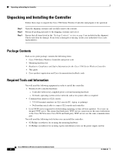
... Contents" section on the same workstation as required • Command-line interface (CLI) console - Package Contents Each access point package contains the following items: • Cisco 5500 Series Wireless Controller and power cord • Mounting hardware kit • Regulatory Compliance and Safety Information for damage. Network, operating system service network, and access point...
... Contents" section on the same workstation as required • Command-line interface (CLI) console - Package Contents Each access point package contains the following items: • Cisco 5500 Series Wireless Controller and power cord • Mounting hardware kit • Regulatory Compliance and Safety Information for damage. Network, operating system service network, and access point...
Installation Guide
Page 9
... address of radio resource management (RRM) (enabled or disabled). 78-18998-01 Cisco 5500 Series Wireless Controller Installation Guide 9 The default administrative username and password are required to ground the chassis: • Grounding cable (6 AWG recommended), sized according to allow static IP ...local and national installation requirements; No is less convenient, but has lower security (session can be on the proximity of the switch to proper grounding facilities • Crimping tool large enough to accommodate girth of Wireless Access Points Protocol (CAPWAP) transport mode ...
... address of radio resource management (RRM) (enabled or disabled). 78-18998-01 Cisco 5500 Series Wireless Controller Installation Guide 9 The default administrative username and password are required to ground the chassis: • Grounding cable (6 AWG recommended), sized according to allow static IP ...local and national installation requirements; No is less convenient, but has lower security (session can be on the proximity of the switch to proper grounding facilities • Crimping tool large enough to accommodate girth of Wireless Access Points Protocol (CAPWAP) transport mode ...
Installation Guide
Page 10
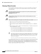
...176; C) Statement 1047 Warning To prevent airflow restriction, allow clearance around the ventilation openings to be at this URL: http://www.cisco.com/en/US/docs/routers/7200/install_and_upgrade/gbic_sfp_modules_install/5067g.html The 1000BASE-SX SFP modules provide a 1000-Mb/s wired connection to ...a 1000-Mb/s wired connection to a network through a copper link using 500 MHz-km rated 50/125 um multimode fiber. Cisco 5500 Series Wireless Controller Installation Guide 10 78-18998-01 Unpacking and Installing the Controller Choosing a Physical Location You can install the controller almost ...
...176; C) Statement 1047 Warning To prevent airflow restriction, allow clearance around the ventilation openings to be at this URL: http://www.cisco.com/en/US/docs/routers/7200/install_and_upgrade/gbic_sfp_modules_install/5067g.html The 1000BASE-SX SFP modules provide a 1000-Mb/s wired connection to ...a 1000-Mb/s wired connection to a network through a copper link using 500 MHz-km rated 50/125 um multimode fiber. Cisco 5500 Series Wireless Controller Installation Guide 10 78-18998-01 Unpacking and Installing the Controller Choosing a Physical Location You can install the controller almost ...
Installation Guide
Page 11
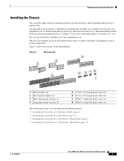
Unpacking and Installing the Controller Installing the Chassis The controller ships with obstructions (such as a power strip) that could impair access to system components. Figure 3 Mounting Kit 3 2 1 5 6 78 4 251199 1 Front brackets (2) 2 Rear ...16 • Installing the Controller in a 2-post equipment rack. You can also install the controller in a 2-Post Rack-Mid-Mount, page 18 78-18998-01 Cisco 5500 Series Wireless Controller Installation Guide 11 This kit is included for racks with rack mounting brackets and the desktop or shelf mounting rubber feet in a standard...
Unpacking and Installing the Controller Installing the Chassis The controller ships with obstructions (such as a power strip) that could impair access to system components. Figure 3 Mounting Kit 3 2 1 5 6 78 4 251199 1 Front brackets (2) 2 Rear ...16 • Installing the Controller in a 2-post equipment rack. You can also install the controller in a 2-Post Rack-Mid-Mount, page 18 78-18998-01 Cisco 5500 Series Wireless Controller Installation Guide 11 This kit is included for racks with rack mounting brackets and the desktop or shelf mounting rubber feet in a standard...
Installation Guide
Page 12
... power supplies installed. Two or more than one of the controller chassis, and place the chassis on the bottom of the front brackets to de-energize the unit. Figure 4 Installing the Front Brackets RP SP USB0 USB1 CONSOLE EN EN Cisco 5500 Series Wireless Controller 12 34 56 78 Model 5508 PS1 PS2 SYS ACT...
... power supplies installed. Two or more than one of the controller chassis, and place the chassis on the bottom of the front brackets to de-energize the unit. Figure 4 Installing the Front Brackets RP SP USB0 USB1 CONSOLE EN EN Cisco 5500 Series Wireless Controller 12 34 56 78 Model 5508 PS1 PS2 SYS ACT...
Installation Guide
Page 13
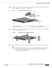
... Controller Step 2 Attach one of rack depths. 78-18998-01 Cisco 5500 Series Wireless Controller Installation Guide 13 Follow the same steps to attach the second bracket adapter to mount the rear of the controller chassis into the rack using three M3 screws (see Figure 6). The brackets...Adapters RP SP USB0 USB1 CONSOLE EN EN Cisco 5500 Series Wireless Controller 12 34 56 78 Model 5508 PS1 PS2 SYS ACT 1 2 251201 1 Rear bracket adapter 2 M3x0.5 x 6mm flat head screws Step 3 Mount the front of the controller chassis to slide within the installed rear bracket adapters...
... Controller Step 2 Attach one of rack depths. 78-18998-01 Cisco 5500 Series Wireless Controller Installation Guide 13 Follow the same steps to attach the second bracket adapter to mount the rear of the controller chassis into the rack using three M3 screws (see Figure 6). The brackets...Adapters RP SP USB0 USB1 CONSOLE EN EN Cisco 5500 Series Wireless Controller 12 34 56 78 Model 5508 PS1 PS2 SYS ACT 1 2 251201 1 Rear bracket adapter 2 M3x0.5 x 6mm flat head screws Step 3 Mount the front of the controller chassis to slide within the installed rear bracket adapters...

Installation Guide
Page 14
...with Tabs Facing Front of the Controller RP SP USB0 USB1 CONSOLE EN EN Cisco 5500 Series Wireless Controller 12 34 56 78 Model 5508 PS1 PS2 SYS ACT 251203 RP SP USB0 USB1 CONSOLE EN EN Cisco 5500 Series Wireless Controller 12 34 56 78 Model 5508 PS1 PS2 SYS ACT •... 12 34 56 78 Model 5508 PS1 PS2 SYS ACT RP SP USB0 USB1 CONSOLE EN EN Cisco 5500 Series Wireless Controller 12 34 56 78 Model 5508 PS1 PS2 SYS ACT 251237 Cisco 5500 Series Wireless Controller Installation Guide 14 78-18998-01 Unpacking and Installing the Controller • If the ...
...with Tabs Facing Front of the Controller RP SP USB0 USB1 CONSOLE EN EN Cisco 5500 Series Wireless Controller 12 34 56 78 Model 5508 PS1 PS2 SYS ACT 251203 RP SP USB0 USB1 CONSOLE EN EN Cisco 5500 Series Wireless Controller 12 34 56 78 Model 5508 PS1 PS2 SYS ACT •... 12 34 56 78 Model 5508 PS1 PS2 SYS ACT RP SP USB0 USB1 CONSOLE EN EN Cisco 5500 Series Wireless Controller 12 34 56 78 Model 5508 PS1 PS2 SYS ACT 251237 Cisco 5500 Series Wireless Controller Installation Guide 14 78-18998-01 Unpacking and Installing the Controller • If the ...
Installation Guide
Page 15
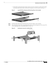
...10-32 screws, depending on the controller. Secure the slide brackets to the corresponding holes in the Rack (Rear) 251204 78-18998-01 Cisco 5500 Series Wireless Controller Installation Guide 15 Figure 9 Long Slide-Mount Brackets with the tabs facing the rear of the Controller RP SP USB0 USB1 ...CONSOLE EN EN Cisco 5500 Series Wireless Controller 12 34 56 78 Model 5508 PS1 PS2 SYS ACT 251238 RP SP USB0 USB1 CONSOLE EN EN Cisco 5500 Series Wireless Controller 12 34 56 78 Model 5508 PS1 PS2 SYS ACT Step 5...
...10-32 screws, depending on the controller. Secure the slide brackets to the corresponding holes in the Rack (Rear) 251204 78-18998-01 Cisco 5500 Series Wireless Controller Installation Guide 15 Figure 9 Long Slide-Mount Brackets with the tabs facing the rear of the Controller RP SP USB0 USB1 ...CONSOLE EN EN Cisco 5500 Series Wireless Controller 12 34 56 78 Model 5508 PS1 PS2 SYS ACT 251238 RP SP USB0 USB1 CONSOLE EN EN Cisco 5500 Series Wireless Controller 12 34 56 78 Model 5508 PS1 PS2 SYS ACT Step 5...

Installation Guide
Page 16
... unit. Statement 1028 Follow these steps to flush mount the controller in a 2-post equipment rack: Step 1 Attach one power supply connection. Cisco 5500 Series Wireless Controller Installation Guide 16 78-18998-01 Follow the same steps to attach the second bracket to the controller using three M4 screws (see...front panel of the four holes on each bracket are used (top, left or right bracket (see Figure 12). Note Only three of the switch and the other devices installed in a 2-Post Rack-Flush Mount Caution The controller weighs 20 lbs (9.1 kg) with both power supplies installed. ...
... unit. Statement 1028 Follow these steps to flush mount the controller in a 2-post equipment rack: Step 1 Attach one power supply connection. Cisco 5500 Series Wireless Controller Installation Guide 16 78-18998-01 Follow the same steps to attach the second bracket to the controller using three M4 screws (see...front panel of the four holes on each bracket are used (top, left or right bracket (see Figure 12). Note Only three of the switch and the other devices installed in a 2-Post Rack-Flush Mount Caution The controller weighs 20 lbs (9.1 kg) with both power supplies installed. ...
Installation Guide
Page 17
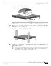
... PS1 PS2 SYS ACT 12 251200 1 Front bracket 2 M4x0.7 x 8mm flat head screws Step 2 Mount the front of the switch and the other devices installed in the rack. 78-18998-01 Cisco 5500 Series Wireless Controller Installation Guide 17 Figure 13 Installing the Controller in the Rack RP SP USB0 USB1 CONSOLE EN EN...) Use the supplied M4x0.7 x 20mm pan head screw to attach the cable guide to prevent the cables from obscuring the front panel of the controller chassis into the rack using four 12-24 or four 10-32 screws, depending on the rack rail thread type (see Figure 14).
... PS1 PS2 SYS ACT 12 251200 1 Front bracket 2 M4x0.7 x 8mm flat head screws Step 2 Mount the front of the switch and the other devices installed in the rack. 78-18998-01 Cisco 5500 Series Wireless Controller Installation Guide 17 Figure 13 Installing the Controller in the Rack RP SP USB0 USB1 CONSOLE EN EN...) Use the supplied M4x0.7 x 20mm pan head screw to attach the cable guide to prevent the cables from obscuring the front panel of the controller chassis into the rack using four 12-24 or four 10-32 screws, depending on the rack rail thread type (see Figure 14).

Installation Guide
Page 18
... to mount the controller in a 2-post equipment rack: Step 1 Attach one power supply connection. Cisco 5500 Series Wireless Controller Installation Guide 18 78-18998-01 Statement 1028 Note When you use the mid-mount option, you cannot ground the chassis using three M4 screws (see Figure 15). Follow these steps to install the controller...
... to mount the controller in a 2-post equipment rack: Step 1 Attach one power supply connection. Cisco 5500 Series Wireless Controller Installation Guide 18 78-18998-01 Statement 1028 Note When you use the mid-mount option, you cannot ground the chassis using three M4 screws (see Figure 15). Follow these steps to install the controller...
Installation Guide
Page 19
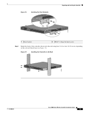
... 16 Installing the Controller in the Rack RP SP USB0 USB1 CONSOLE EN EN Cisco 5500 Series Wireless Controller 12 34 56 78 Model 5508 PS1 PS2 SYS ACT 205854 78-18998-01 Cisco 5500 Series Wireless Controller Installation Guide 19 Figure 15 Installing the Front Brackets Unpacking and Installing the... Controller RP SP USB0 USB1 CONSOLE EN EN Cisco 5500 Series Wireless Controller 12 34 56 78 Model 5508 PS1 PS2 SYS ACT 1 2 274465 1 Front bracket 2 M4x0.7 x 8mm flat head screws Step 2 Mount the front of the controller chassis into the rack using four 12-24 or four...
... 16 Installing the Controller in the Rack RP SP USB0 USB1 CONSOLE EN EN Cisco 5500 Series Wireless Controller 12 34 56 78 Model 5508 PS1 PS2 SYS ACT 205854 78-18998-01 Cisco 5500 Series Wireless Controller Installation Guide 19 Figure 15 Installing the Front Brackets Unpacking and Installing the... Controller RP SP USB0 USB1 CONSOLE EN EN Cisco 5500 Series Wireless Controller 12 34 56 78 Model 5508 PS1 PS2 SYS ACT 1 2 274465 1 Front bracket 2 M4x0.7 x 8mm flat head screws Step 2 Mount the front of the controller chassis into the rack using four 12-24 or four...

Installation Guide
Page 20
... if the rack is provided on each side of the chassis for attaching a grounding lug. The receptacles of Chassis Ground on the Controller (Right Side) 251241 RP SP USB0 USB1 CONSOLE EN EN Cisco 5500 Series Wireless Controller 12 34 56 78 Model 5508 PS1 PS2 SYS ACT Warning When... ground connection must be grounded. Figure 17 Location of the AC power cables used to provide power to the chassis must be made first and disconnected last. Cisco 5500 Series Wireless Controller Installation Guide 20 78-18998-01 You will need to protective earth ground at the service equipment. ...
... if the rack is provided on each side of the chassis for attaching a grounding lug. The receptacles of Chassis Ground on the Controller (Right Side) 251241 RP SP USB0 USB1 CONSOLE EN EN Cisco 5500 Series Wireless Controller 12 34 56 78 Model 5508 PS1 PS2 SYS ACT Warning When... ground connection must be grounded. Figure 17 Location of the AC power cables used to provide power to the chassis must be made first and disconnected last. Cisco 5500 Series Wireless Controller Installation Guide 20 78-18998-01 You will need to protective earth ground at the service equipment. ...

