
Hardware Installation Guide
Page 8
...or Connecting Devices to the Switch 1-12 Product Overview 2-1 Features 2-1 Front Panel Description 2-3 10/100 and 10/100/1000 Ports 2-6 SFP Module Slots 2-7 SFP Modules 2-7 LEDs 2-8 System LED 2-9 RPS LED 2-9 Master LED 2-10 Port LEDs and Modes 2-10 Rear Panel Description 2-14 StackWise ...Ports 2-15 Power Connectors 2-16 Internal Power Supply Connector 2-16 Cisco RPS Connector 2-16 Console Port 2-17 Management Options 2-18 Network Configurations 2-19 ...
...or Connecting Devices to the Switch 1-12 Product Overview 2-1 Features 2-1 Front Panel Description 2-3 10/100 and 10/100/1000 Ports 2-6 SFP Module Slots 2-7 SFP Modules 2-7 LEDs 2-8 System LED 2-9 RPS LED 2-9 Master LED 2-10 Port LEDs and Modes 2-10 Rear Panel Description 2-14 StackWise ...Ports 2-15 Power Connectors 2-16 Internal Power Supply Connector 2-16 Cisco RPS Connector 2-16 Console Port 2-17 Management Options 2-18 Network Configurations 2-19 ...

Hardware Installation Guide
Page 10
...Slots 3-43 Connecting to the 10/100 and 10/100/1000 Ports 3-44 Connecting to an SFP Module 3-46 Connecting to a Fiber-Optic SFP Module 3-47 Connecting to 1000BASE-T SFP Modules 3-48 Where to Go Next 3-50 4 C H A P T E R ...Specifications A-1 B A P P E N D I X Connector and Cable Specifications B-1 Connector Specifications B-1 10/100/1000 Ports B-1 Connecting to 1000BASE-T Devices B-2 10/100 Ports B-3 SFP Module Ports B-5 Console Port B-6 Cable and Adapter Specifications B-6 Two Twisted-Pair Cable Pinouts B-6 Four Twisted-Pair Cable Pinouts for 10/100 Ports B-7 Four Twisted-Pair...
...Slots 3-43 Connecting to the 10/100 and 10/100/1000 Ports 3-44 Connecting to an SFP Module 3-46 Connecting to a Fiber-Optic SFP Module 3-47 Connecting to 1000BASE-T SFP Modules 3-48 Where to Go Next 3-50 4 C H A P T E R ...Specifications A-1 B A P P E N D I X Connector and Cable Specifications B-1 Connector Specifications B-1 10/100/1000 Ports B-1 Connecting to 1000BASE-T Devices B-2 10/100 Ports B-3 SFP Module Ports B-5 Console Port B-6 Cable and Adapter Specifications B-6 Two Twisted-Pair Cable Pinouts B-6 Four Twisted-Pair Cable Pinouts for 10/100 Ports B-7 Four Twisted-Pair...

Hardware Installation Guide
Page 33
...-15136-02 Catalyst 3750 Switch Hardware Installation Guide 1-5 Step 4 Connect the Ethernet cable (not included) to a 10/100 Ethernet port or small form-factor pluggable (SFP) module port on page 4-2. For more information, see the "Clearing the Switch IP Address and Configuration" section on the front panel of the LEDs begin...
...-15136-02 Catalyst 3750 Switch Hardware Installation Guide 1-5 Step 4 Connect the Ethernet cable (not included) to a 10/100 Ethernet port or small form-factor pluggable (SFP) module port on page 4-2. For more information, see the "Clearing the Switch IP Address and Configuration" section on the front panel of the LEDs begin...

Hardware Installation Guide
Page 42
Connection for optional Cisco RPS 300 redundant power system that operates on AC input and supplies backup DC power output to nine switches in half-duplex mode at 10, ... can either operate at 10 or 100 Mbps. • Configuration - For 10/100 ports, autonegotiates the speed and duplex settings - Catalyst 3750-24TS-24 10/100 Ethernet ports and 2 small form-factor pluggable (SFP) module slots - StackWise ports are not user-configurable. • Switches are the switch features: • Hardware - Catalyst 3750G...
Connection for optional Cisco RPS 300 redundant power system that operates on AC input and supplies backup DC power output to nine switches in half-duplex mode at 10, ... can either operate at 10 or 100 Mbps. • Configuration - For 10/100 ports, autonegotiates the speed and duplex settings - Catalyst 3750-24TS-24 10/100 Ethernet ports and 2 small form-factor pluggable (SFP) module slots - StackWise ports are not user-configurable. • Switches are the switch features: • Hardware - Catalyst 3750G...

Hardware Installation Guide
Page 43
...member (port 2) on the left ) and 2 (right). The first member of Catalyst 3750 switches. Connection for optional Cisco RPS 675 redundant power system that operates on the Catalyst 3750G-24T and 3750G-24TS are numbered 1 (left , as shown in pairs. The ports are numbered 1 through 24. Front Panel Description The ...ports on AC input and supplies backup DC power output to 28. 78-15136-02 Catalyst 3750 Switch Hardware Installation Guide 2-3 In Figure 2-3 the SFP port are numbered 25 to the family of the pair (port 1) is above the second member (port 2) on the far left, as shown...
...member (port 2) on the left ) and 2 (right). The first member of Catalyst 3750 switches. Connection for optional Cisco RPS 675 redundant power system that operates on the Catalyst 3750G-24T and 3750G-24TS are numbered 1 (left , as shown in pairs. The ports are numbered 1 through 24. Front Panel Description The ...ports on AC input and supplies backup DC power output to 28. 78-15136-02 Catalyst 3750 Switch Hardware Installation Guide 2-3 In Figure 2-3 the SFP port are numbered 25 to the family of the pair (port 1) is above the second member (port 2) on the far left, as shown...

Hardware Installation Guide
Page 44
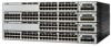
... 78-15136-02 The ports are numbered 1 through 12. Front Panel Description Figure 2-2 Catalyst 3750G-24T Front Panel SYST RPS MASTR STAT DUPLX SPEED STACK MODE 12 1X 34 56 78 9 10 11 ...20 21 22 23 24 23X 14X 24X 1 Catalyst 3750 SERIES 1 10/100/1000 ports Figure 2-3 Catalyst 3750G-24TS Front Panel Chapter 2 Product Overview 86543 86544 SYST RPS MASTR STAT DUPLX SPEED STACK MODE 12 1X 34 56 ... 24X Catalyst 3750 SERIES 25 26 27 28 1 2 1 10/100 ports 2 SFP module ports The Catalyst 3750G-12S SFP module slots are grouped in three sets of four, as shown in Figure 2-4.
... 78-15136-02 The ports are numbered 1 through 12. Front Panel Description Figure 2-2 Catalyst 3750G-24T Front Panel SYST RPS MASTR STAT DUPLX SPEED STACK MODE 12 1X 34 56 78 9 10 11 ...20 21 22 23 24 23X 14X 24X 1 Catalyst 3750 SERIES 1 10/100/1000 ports Figure 2-3 Catalyst 3750G-24TS Front Panel Chapter 2 Product Overview 86543 86544 SYST RPS MASTR STAT DUPLX SPEED STACK MODE 12 1X 34 56 ... 24X Catalyst 3750 SERIES 25 26 27 28 1 2 1 10/100 ports 2 SFP module ports The Catalyst 3750G-12S SFP module slots are grouped in three sets of four, as shown in Figure 2-4.

Hardware Installation Guide
Page 45
... 39 40 41 42 43 44 45 46 47 48 47X 32X 34X 48X Catalyst 3750 SERIES 1 3 2 4 1 2 1 10/100 ports 2 SFP module ports 78-15136-02 Catalyst 3750 Switch Hardware Installation Guide 2-5 Chapter 2 Product Overview Figure 2-4 Catalyst 3750G-12S Front Panel Front Panel Description 97166 SYST... RPS MASTR STAT DUPLX SPEED STACK MODE 1 2 3 4 5 6 7 8 9 10 Catalyst 3750 SERIES 11 12 1 1 SFP module ports The Catalyst 3750-48TS 10/100 ports are 1 (top) and 2 (bottom) and so on. The ports are grouped in Figure 2-1. Port 3 is above...
... 39 40 41 42 43 44 45 46 47 48 47X 32X 34X 48X Catalyst 3750 SERIES 1 3 2 4 1 2 1 10/100 ports 2 SFP module ports 78-15136-02 Catalyst 3750 Switch Hardware Installation Guide 2-5 Chapter 2 Product Overview Figure 2-4 Catalyst 3750G-12S Front Panel Front Panel Description 97166 SYST... RPS MASTR STAT DUPLX SPEED STACK MODE 1 2 3 4 5 6 7 8 9 10 Catalyst 3750 SERIES 11 12 1 1 SFP module ports The Catalyst 3750-48TS 10/100 ports are 1 (top) and 2 (bottom) and so on. The ports are grouped in Figure 2-1. Port 3 is above...

Hardware Installation Guide
Page 47
Chapter 2 Product Overview Front Panel Description SFP Module Slots The SFP module slots support the SFP modules listed in an SFP module slot. The Catalyst 3750 models support these Cisco SFP options: • 1000BASE-LX • 1000BASE-SX • 1000BASE-T For more information about these SFP modules, refer to establish fiber-optic connections. You use Category 5 cable with...
Chapter 2 Product Overview Front Panel Description SFP Module Slots The SFP module slots support the SFP modules listed in an SFP module slot. The Catalyst 3750 models support these Cisco SFP options: • 1000BASE-LX • 1000BASE-SX • 1000BASE-T For more information about these SFP modules, refer to establish fiber-optic connections. You use Category 5 cable with...

Hardware Installation Guide
Page 50
...LED Port Mode Off Green Amber Description Switch is highlighted. Table 2-4 lists the mode LEDs and their meanings. Note The Cisco RPS 300 does not support the Catalyst 3750G-24TS switches. To select or change port modes, the meanings of information displayed through the port LEDs. These port LEDs, as...master or a standalone switch. Port LEDs and Modes Each RJ-45 port and SFP module slot has a port LED. The port modes determine the type of the port LED colors also change to the Cisco RPS 300 Redundant Power System Hardware Installation Guide. Table 2-2 lists the LED colors...
...LED Port Mode Off Green Amber Description Switch is highlighted. Table 2-4 lists the mode LEDs and their meanings. Note The Cisco RPS 300 does not support the Catalyst 3750G-24TS switches. To select or change port modes, the meanings of information displayed through the port LEDs. These port LEDs, as...master or a standalone switch. Port LEDs and Modes Each RJ-45 port and SFP module slot has a port LED. The port modes determine the type of the port LED colors also change to the Cisco RPS 300 Redundant Power System Hardware Installation Guide. Table 2-2 lists the LED colors...

Hardware Installation Guide
Page 52
... ports (on the switch rear panel) are up, and the representative stack LEDs are amber when the ports are down: • SFP port LEDs 1 and 2 on the Catalyst 3750-24TS switch show the position of other stack member switches. Green Member number of a stack. For example, if you press the Mode button...
... ports (on the switch rear panel) are up, and the representative stack LEDs are amber when the ports are down: • SFP port LEDs 1 and 2 on the Catalyst 3750-24TS switch show the position of other stack member switches. Green Member number of a stack. For example, if you press the Mode button...

Hardware Installation Guide
Page 53
...1 and 2, respectively. Chapter 2 Product Overview Front Panel Description • SFP port LEDs 3 and 4 on the Catalyst 3750-48TS switch show the status for StackWise ports 1 and 2, respectively. • SFP port LEDs 27 and 28 on the Catalyst 3750G-24TS switch show the status for StackWise ports 1 and 2, respectively. •... The 10/100/1000 port LEDs 23 and 24 on the Catalyst 3750G-24T switch show the status for StackWise ports 1 and 2, respectively. • SFP port LEDs 11 and 12 on all the switches in the stack, the stack is not operating at full ...
...1 and 2, respectively. Chapter 2 Product Overview Front Panel Description • SFP port LEDs 3 and 4 on the Catalyst 3750-48TS switch show the status for StackWise ports 1 and 2, respectively. • SFP port LEDs 27 and 28 on the Catalyst 3750G-24TS switch show the status for StackWise ports 1 and 2, respectively. •... The 10/100/1000 port LEDs 23 and 24 on the Catalyst 3750G-24T switch show the status for StackWise ports 1 and 2, respectively. • SFP port LEDs 11 and 12 on all the switches in the stack, the stack is not operating at full ...

Hardware Installation Guide
Page 61
...; Connecting StackWise Cable to StackWise Ports, page 3-37 • Connecting to the 10/100 and 10/100/1000 Ports, page 3-44 • Connecting to an SFP Module, page 3-46 • Where to Go Next, page 3-50 Preparing for Installation This section covers these topics: • Warnings, page 3-2 • EMC Regulatory Statements...
...; Connecting StackWise Cable to StackWise Ports, page 3-37 • Connecting to the 10/100 and 10/100/1000 Ports, page 3-44 • Connecting to an SFP Module, page 3-46 • Where to Go Next, page 3-50 Preparing for Installation This section covers these topics: • Warnings, page 3-2 • EMC Regulatory Statements...

Hardware Installation Guide
Page 66
.... Access to ports is within the ranges listed in an elevated bit error rate (BER). Table 3-1 Fiber-Optic SFP Module Port Cabling Specifications SFP Module Wavelength (nanometers) Fiber Type Core Size (micron) Modal Bandwidth (MHz/km) Cable Distance 1000BASE-SX 850 1000BASE-LX/LH 1300 MMF 62.5 160 62.5 ... and the MMF cable on both the sending and receiving ends of the link. When using the LX/LH SFP module with MMF, 1000BASE-LX/LH SFP modules, and a short link distance can be sure to observe these requirements: • For 10/100 and 10/100/1000 ports, cable lengths from the...
.... Access to ports is within the ranges listed in an elevated bit error rate (BER). Table 3-1 Fiber-Optic SFP Module Port Cabling Specifications SFP Module Wavelength (nanometers) Fiber Type Core Size (micron) Modal Bandwidth (MHz/km) Cable Distance 1000BASE-SX 850 1000BASE-LX/LH 1300 MMF 62.5 160 62.5 ... and the MMF cable on both the sending and receiving ends of the link. When using the LX/LH SFP module with MMF, 1000BASE-LX/LH SFP modules, and a short link distance can be sure to observe these requirements: • For 10/100 and 10/100/1000 ports, cable lengths from the...

Hardware Installation Guide
Page 90
... shown in the stacks. See the "Connecting to the 10/100 and 10/100/1000 Ports" section on page 3-44 and the "Connecting to an SFP Module" section on page 3-46 to the Console Port" section on page 1-4 and the "Starting the Terminal Emulation Software" section on page 1-6. • Power on...
... shown in the stacks. See the "Connecting to the 10/100 and 10/100/1000 Ports" section on page 3-44 and the "Connecting to an SFP Module" section on page 3-46 to the Console Port" section on page 1-4 and the "Starting the Terminal Emulation Software" section on page 1-6. • Power on...

Hardware Installation Guide
Page 96
Attach the four rubber feet to an SFP Module" section on the table or shelf near an AC power source. If the switches are stacked, see the "Powering Considerations" section on the bottom ...> prompt through the console port by using a terminal program or through the network by using Telnet. Table or Shelf Mounting Follow these tasks to an SFP Module" section on the switch. See the "Connecting to the 10/100 and 10/100/1000 Ports" section on page 3-44 and the "Connecting to...
Attach the four rubber feet to an SFP Module" section on the table or shelf near an AC power source. If the switches are stacked, see the "Powering Considerations" section on the bottom ...> prompt through the console port by using a terminal program or through the network by using Telnet. Table or Shelf Mounting Follow these tasks to an SFP Module" section on the switch. See the "Connecting to the 10/100 and 10/100/1000 Ports" section on page 3-44 and the "Connecting to...

Hardware Installation Guide
Page 100
... for the switch. 3-40 Catalyst 3750 Switch Hardware Installation Guide 78-15136-02 SFP modules are inserted into SFP module slots on the Catalyst 3750 switch. This encoding provides a way for Cisco to install and remove SFP modules. Installing and Removing SFP Modules Chapter 3 Switch Installation Figure 3-36 Incorrect Removal of the cable, and the...
... for the switch. 3-40 Catalyst 3750 Switch Hardware Installation Guide 78-15136-02 SFP modules are inserted into SFP module slots on the Catalyst 3750 switch. This encoding provides a way for Cisco to install and remove SFP modules. Installing and Removing SFP Modules Chapter 3 Switch Installation Figure 3-36 Incorrect Removal of the cable, and the...

Hardware Installation Guide
Page 101
...useful life. Caution We strongly recommend that you do not install or remove fiber-optic SFP modules with a Bale-Clasp Latch 86575 To insert an SFP module into SFP Module Slots Figure 3-37 shows an SFP module that identify the top side of the potential damage to the cables, the cable... connector, or the optical interfaces in the SFP module. Find the send (TX) and receive (RX) markings that has a bale-clasp latch. Installing SFP Modules into the SFP module slot, follow these steps: Step 1 Step 2 Attach an ESD-preventive wrist strap ...
...useful life. Caution We strongly recommend that you do not install or remove fiber-optic SFP modules with a Bale-Clasp Latch 86575 To insert an SFP module into SFP Module Slots Figure 3-37 shows an SFP module that identify the top side of the potential damage to the cables, the cable... connector, or the optical interfaces in the SFP module. Find the send (TX) and receive (RX) markings that has a bale-clasp latch. Installing SFP Modules into the SFP module slot, follow these steps: Step 1 Step 2 Attach an ESD-preventive wrist strap ...

Hardware Installation Guide
Page 102
...or the rubber caps from the fiber-optic cable until you are ready to connect the cable. Insert the SFP module into the slot until you feel the connector on the module snap into an SFP Module Slot 13 13X 5 6 7 14X 8 9 10 Catalyst 3750 SERIES 11 12 97169 Step 5 ...the dust plugs from contamination and ambient light. 3-42 Catalyst 3750 Switch Hardware Installation Guide 78-15136-02 Installing and Removing SFP Modules Chapter 3 Switch Installation Note On some SFP modules, the send and receive (TX and RX) markings might be replaced by arrows that show the direction of the ...
...or the rubber caps from the fiber-optic cable until you are ready to connect the cable. Insert the SFP module into the slot until you feel the connector on the module snap into an SFP Module Slot 13 13X 5 6 7 14X 8 9 10 Catalyst 3750 SERIES 11 12 97169 Step 5 ...the dust plugs from contamination and ambient light. 3-42 Catalyst 3750 Switch Hardware Installation Guide 78-15136-02 Installing and Removing SFP Modules Chapter 3 Switch Installation Note On some SFP modules, the send and receive (TX and RX) markings might be replaced by arrows that show the direction of the ...
Hardware Installation Guide
Page 103
...Figure 3-39. Chapter 3 Switch Installation Installing and Removing SFP Modules Step 6 Insert the cable connector into the SFP module: • For fiber-optic SFP modules, insert the LC or MT-RJ cable connector into the SFP module. • For copper SFP modules, insert the RJ-45 cable connector into the ...use a small, flat-blade screwdriver or other long, narrow instrument to a bare metal surface on the chassis. Note When connecting to 1000BASE-T SFP modules, be sure to eject the module. Tip For reattachment, note which cable connector plug is send (TX) and which is obstructed and ...
...Figure 3-39. Chapter 3 Switch Installation Installing and Removing SFP Modules Step 6 Insert the cable connector into the SFP module: • For fiber-optic SFP modules, insert the LC or MT-RJ cable connector into the SFP module. • For copper SFP modules, insert the RJ-45 cable connector into the ...use a small, flat-blade screwdriver or other long, narrow instrument to a bare metal surface on the chassis. Note When connecting to 1000BASE-T SFP modules, be sure to eject the module. Tip For reattachment, note which cable connector plug is send (TX) and which is obstructed and ...
Hardware Installation Guide
Page 104
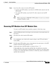
... • Set the port speed and duplex parameters on both ends of attached devices. Place the removed SFP module in no linkage. Connecting to the 10/100 and 10/100/1000 Ports The switch 10/100 ... 10/100 and 10/100/1000 Ports Chapter 3 Switch Installation Figure 3-39 Removing a Bale-Clasp Latch SFP Module by Using a Flat-Blade Screwdriver 86554 13 13X 14 15 16 17 18 19 20 21 22... 23 24 23X 14X 24X Catalyst 3750 SERIES 1 2 1 1 Bale clasp Step 5 Step 6 Grasp the SFP module between your thumb and index finger, and carefully remove it from the module slot. If the attached ports ...
... • Set the port speed and duplex parameters on both ends of attached devices. Place the removed SFP module in no linkage. Connecting to the 10/100 and 10/100/1000 Ports The switch 10/100 ... 10/100 and 10/100/1000 Ports Chapter 3 Switch Installation Figure 3-39 Removing a Bale-Clasp Latch SFP Module by Using a Flat-Blade Screwdriver 86554 13 13X 14 15 16 17 18 19 20 21 22... 23 24 23X 14X 24X Catalyst 3750 SERIES 1 2 1 1 Bale clasp Step 5 Step 6 Grasp the SFP module between your thumb and index finger, and carefully remove it from the module slot. If the attached ports ...

