
Getting Started Guide
Page 1
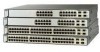
GETTING STARTED GUIDE Catalyst 3750 Switch Getting Started Guide 1 About this Guide 2 Taking Out What You Need 3 Running Express Setup 4 Managing the Switch 5 Planning Switch Stacks 6 Rack-Mounting 7 In Case of Difficulty 8 Obtaining Documentation, Obtaining Support, and Security Guidelines 9 Cisco Warranty Information
GETTING STARTED GUIDE Catalyst 3750 Switch Getting Started Guide 1 About this Guide 2 Taking Out What You Need 3 Running Express Setup 4 Managing the Switch 5 Planning Switch Stacks 6 Rack-Mounting 7 In Case of Difficulty 8 Obtaining Documentation, Obtaining Support, and Security Guidelines 9 Cisco Warranty Information
Getting Started Guide
Page 2
..., and troubleshooting help. The software version is missing or damaged, contact your Catalyst switch. For additional installation and configuration information for Catalyst 3750 switches, see the release notes, also on Cisco.com. For translations of the StackWise cable, the 0.5-meter cable is supplied....packing material to the shipping container, and save it for future use Express Setup to initially configure your Cisco representative or reseller for the Catalyst 3750 Switch that accompanies this equipment to supply this guide. 2 Taking Out What You Need Follow these steps:...
..., and troubleshooting help. The software version is missing or damaged, contact your Catalyst switch. For additional installation and configuration information for Catalyst 3750 switches, see the release notes, also on Cisco.com. For translations of the StackWise cable, the 0.5-meter cable is supplied....packing material to the shipping container, and save it for future use Express Setup to initially configure your Cisco representative or reseller for the Catalyst 3750 Switch that accompanies this equipment to supply this guide. 2 Taking Out What You Need Follow these steps:...

Getting Started Guide
Page 3
... 16X 18X 33 31X 33X 34 35 36 37 38 39 40 41 42 43 44 45 46 47 48 47X 32X 34X Catalyst 3750G SERIES 49 51 Catalyst 3750 switch 48X 50 52 0.5-meter, 1.0-meter or 3.0-meter StackWise cable Two 19-inch mounting brackets Four number-12 Phillips machine screws Four number...
... 16X 18X 33 31X 33X 34 35 36 37 38 39 40 41 42 43 44 45 46 47 48 47X 32X 34X Catalyst 3750G SERIES 49 51 Catalyst 3750 switch 48X 50 52 0.5-meter, 1.0-meter or 3.0-meter StackWise cable Two 19-inch mounting brackets Four number-12 Phillips machine screws Four number...
Getting Started Guide
Page 4
... connect to temporarily use Express Setup to the switch. If your PC has a static IP address, change your switch fails POST. Wait for the switch to complete POST, which can then access the switch through the IP address for 3 seconds. Contact your Cisco technical support representative if your PC settings before you begin to a grounded...
... connect to temporarily use Express Setup to the switch. If your PC has a static IP address, change your switch fails POST. Wait for the switch to complete POST, which can then access the switch through the IP address for 3 seconds. Contact your Cisco technical support representative if your PC settings before you begin to a grounded...

Getting Started Guide
Page 5
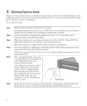
... cable to any 10/100 or 10/100/1000 Ethernet port on your PC. Step 7 Connect a Category 5 Ethernet cable to the Ethernet port on the switch front panel. SYST RPS MASTR STAT DUPLX SPEED STACK MODE 1 1X 2X 23 45 67 89 10 11 12 13 14 15 16 17 15X... 28 29 30 31 32 33 31X 33X 34 35 36 37 38 39 40 41 42 43 44 45 46 47 48 Catalyst 3560G SERIES PoE-48 47X 32X 34X 49 51 48X 50 52 Step 8 Step 9 Verify that the switch and PC Ethernet ports LEDs are green. Wait 30 seconds.
... cable to any 10/100 or 10/100/1000 Ethernet port on your PC. Step 7 Connect a Category 5 Ethernet cable to the Ethernet port on the switch front panel. SYST RPS MASTR STAT DUPLX SPEED STACK MODE 1 1X 2X 23 45 67 89 10 11 12 13 14 15 16 17 15X... 28 29 30 31 32 33 31X 33X 34 35 36 37 38 39 40 41 42 43 44 45 46 47 48 Catalyst 3560G SERIES PoE-48 47X 32X 34X 49 51 48X 50 52 Step 8 Step 9 Verify that the switch and PC Ethernet ports LEDs are green. Wait 30 seconds.
Getting Started Guide
Page 6
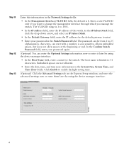
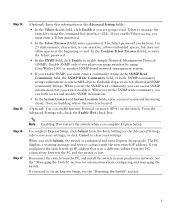
... the Optional Settings information now or enter it later by using the device manager interface: • In the Host Name field, enter a name for the switch. The host name is 1 to 25 alphanumeric characters, can be from 1 to 1001. • In the IP Address field, enter the IP address... the System Date, System Time, and Time Zone fields. The VLAN ID range is limited to change the management interface through which you manage the switch. The password can start with a number, is 1. Click Enable to enable daylight saving time. (Optional) Click the Advanced Settings tab on the Express...
... the Optional Settings information now or enter it later by using the device manager interface: • In the Host Name field, enter a name for the switch. The host name is 1 to 25 alphanumeric characters, can be from 1 to 1001. • In the IP Address field, enter the IP address... the System Date, System Time, and Time Zone fields. The VLAN ID range is limited to change the management interface through which you manage the switch. The password can start with a number, is 1. Click Enable to enable daylight saving time. (Optional) Click the Advanced Settings tab on the Express...
Getting Started Guide
Page 7
...is configured and exits Express Setup mode. When you set the SNMP read community, you can enable Internet Protocol version 6 (IPv6) on the switch. To complete Express Setup, click Submit from 1 to clear your production network. If you need to connect with an IP address that is...• In the Telnet Access field, click Enable if you are not allowed in SNMP community strings. SNMP community strings authenticate access to manage the switch by using the command-line interface (CLI). If you must enter a Telnet password. • In the Telnet Password field, enter a password....
...is configured and exits Express Setup mode. When you set the SNMP read community, you can enable Internet Protocol version 6 (IPv6) on the switch. To complete Express Setup, click Submit from 1 to clear your production network. If you need to connect with an IP address that is...• In the Telnet Access field, click Enable if you are not allowed in SNMP community strings. SNMP community strings authenticate access to manage the switch by using the command-line interface (CLI). If you must enter a Telnet password. • In the Telnet Password field, enter a password....
Getting Started Guide
Page 8
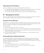
... manager online help for more advanced configuration, download and run on your PC or workstation. 2. Launch a web browser on your PC. Downloading Cisco Network Assistant Cisco Network Assistant is in the switch memory. For more information. 4. Find the Network Assistant installer. 8 The device manager page appears. 3. Use the device manager to manage the...
... manager online help for more advanced configuration, download and run on your PC or workstation. 2. Launch a web browser on your PC. Downloading Cisco Network Assistant Cisco Network Assistant is in the switch memory. For more information. 4. Find the Network Assistant installer. 8 The device manager page appears. 3. Use the device manager to manage the...
Getting Started Guide
Page 9
...: 1. Other Management Options You can enter Cisco IOS commands and parameters through a Telnet session from an SNMP-compatible workstation that is a network management device that works with embedded Cisco Networking Services (CNS) agents in the switch software. Refer to complete the Network Assistant... installation. Start a terminal-emulation program on the switch. 3. In the final panel, click Finish to the ...
...: 1. Other Management Options You can enter Cisco IOS commands and parameters through a Telnet session from an SNMP-compatible workstation that is a network management device that works with embedded Cisco Networking Services (CNS) agents in the switch software. Refer to complete the Network Assistant... installation. Start a terminal-emulation program on the switch. 3. In the final panel, click Finish to the ...
Getting Started Guide
Page 10
...Depending on stack master elections, see the Catalyst 3750 Switch Hardware Installation Guide. If you power the switches in a stack: • The sequence in which switch becomes the stack master, power on switches running releases earlier than Cisco IOS Release 12.2(20)SE3. For cable...• The size of the Catalyst 3750 Switch Hardware Installation Guide for which the switches are initially powered on might need different sized cables. Stacking together switches of your Cisco supplier. See the"Technical Specifications" appendix of the switch. For more information on the ...
...Depending on stack master elections, see the Catalyst 3750 Switch Hardware Installation Guide. If you power the switches in a stack: • The sequence in which switch becomes the stack master, power on switches running releases earlier than Cisco IOS Release 12.2(20)SE3. For cable...• The size of the Catalyst 3750 Switch Hardware Installation Guide for which the switches are initially powered on might need different sized cables. Stacking together switches of your Cisco supplier. See the"Technical Specifications" appendix of the switch. For more information on the ...
Getting Started Guide
Page 11
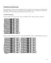
86586 Cabling Considerations These illustrations show the recommended Catalyst 3750 switch stack configurations with redundant StackWise cabling connections for optimized stack bandwidth. For more configuration examples, see the Catalyst 3750 Switch Hardware Installation Guide on Cisco.com. In this example, the stack uses the 0.5-meter StackWise cable to make redundant connections. Vertical Stacking In this example, the stacks use both 0.5- and 3-meter StackWise cables to make redundant connections. 11 86585
86586 Cabling Considerations These illustrations show the recommended Catalyst 3750 switch stack configurations with redundant StackWise cabling connections for optimized stack bandwidth. For more configuration examples, see the Catalyst 3750 Switch Hardware Installation Guide on Cisco.com. In this example, the stack uses the 0.5-meter StackWise cable to make redundant connections. Vertical Stacking In this example, the stacks use both 0.5- and 3-meter StackWise cables to make redundant connections. 11 86585
Getting Started Guide
Page 12
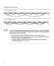
... rack, load the rack from the bottom to ensure that the system remains stable. Statement 1006 12 and 3-meter StackWise cables. In this example, nine switches are stacked side-by-side with redundant connections by using 0.5- and 3-meter StackWise cables. 86825 90532 Warning To prevent bodily injury when mounting or servicing... the rack is the only unit in the rack. • When mounting this unit in the rack. Side-By-Side Stacking In this example, eight switches are stacked side-by-side with redundant connections by using 0.5-
... rack, load the rack from the bottom to ensure that the system remains stable. Statement 1006 12 and 3-meter StackWise cables. In this example, nine switches are stacked side-by-side with redundant connections by using 0.5- and 3-meter StackWise cables. 86825 90532 Warning To prevent bodily injury when mounting or servicing... the rack is the only unit in the rack. • When mounting this unit in the rack. Side-By-Side Stacking In this example, eight switches are stacked side-by-side with redundant connections by using 0.5-
Getting Started Guide
Page 13
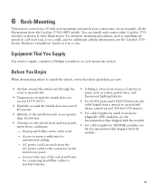
...from the AC power outlet to the switch front and rear panels meets these illustrations. For alternate mounting procedures, such as shown in a 24-inch rack or on Cisco.com. As an example, all the illustrations show the Catalyst 3750G-48TS switch. Before You Begin When determining where to... rack-mount the switch. 6 Rack-Mounting This section covers basic 19-inch rack-mounting and...
...from the AC power outlet to the switch front and rear panels meets these illustrations. For alternate mounting procedures, such as shown in a 24-inch rack or on Cisco.com. As an example, all the illustrations show the Catalyst 3750G-48TS switch. Before You Begin When determining where to... rack-mount the switch. 6 Rack-Mounting This section covers basic 19-inch rack-mounting and...

Getting Started Guide
Page 14
...the heaviest component at least 3 inches (7.6 cm) of these warning statements appear in the rack. Statement 148 Warning To prevent the switch from the bottom to be mounted at the bottom of the rack. • If the rack is the only unit in the... with stabilizing devices, install the stabilizers before mounting or servicing the unit in the Regulatory Compliance and Safety Information for the Catalyst 3750 Switch guide. Installation Warning Statements This section includes the basic installation warning statements. Warning Only trained and qualified personnel should be grounded...
...the heaviest component at least 3 inches (7.6 cm) of these warning statements appear in the rack. Statement 148 Warning To prevent the switch from the bottom to be mounted at the bottom of the rack. • If the rack is the only unit in the... with stabilizing devices, install the stabilizers before mounting or servicing the unit in the Regulatory Compliance and Safety Information for the Catalyst 3750 Switch guide. Installation Warning Statements This section includes the basic installation warning statements. Warning Only trained and qualified personnel should be grounded...
Getting Started Guide
Page 15
...the hazard. A restricted access area can be connected through the use of a special tool, lock and key or other means of the switch. Statement 1044 Warning Voltages that present a shock hazard may exist on the back of security. Statement 265 Warning Class 1 laser product. ... circuit protection: 10/100/1000 Ethernet. Statement 1008 Warning For connections outside the building where the equipment is not connected to the switch, install an RPS connector cover on Power over Ethernet (PoE) circuits if interconnections are made using uninsulated exposed metal contacts, conductors,...
...the hazard. A restricted access area can be connected through the use of a special tool, lock and key or other means of the switch. Statement 1044 Warning Voltages that present a shock hazard may exist on the back of security. Statement 265 Warning Class 1 laser product. ... circuit protection: 10/100/1000 Ethernet. Statement 1008 Warning For connections outside the building where the equipment is not connected to the switch, install an RPS connector cover on Power over Ethernet (PoE) circuits if interconnections are made using uninsulated exposed metal contacts, conductors,...

Getting Started Guide
Page 16
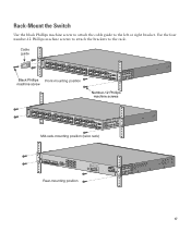
...the Brackets Use four Phillips flat-head screws to attach the long side of the brackets to Catalyst 3750 switches in one of three mounting positions. SYST RPS MASTR STAT DUPLX SPEED STACK MODE 1 1X 2X... 31X 33X 34 35 36 37 38 39 40 41 42 43 44 45 46 47 48 47X 32X 34X Catalyst 3750G SERIES 49 51 48X 50 52 Front-mounting position SYST RPS MASTR STAT DUPLX SPEED STACK MODE 1 1X... 33 31X 33X 34 35 36 37 38 39 40 41 42 43 44 45 46 47 48 47X 32X 34X Catalyst 3750G SERIES 49 51 48X 50 52 Mid-rack-mounting position (telco rack) Number-8 Phillips flat-head screws STACK 1...
...the Brackets Use four Phillips flat-head screws to attach the long side of the brackets to Catalyst 3750 switches in one of three mounting positions. SYST RPS MASTR STAT DUPLX SPEED STACK MODE 1 1X 2X... 31X 33X 34 35 36 37 38 39 40 41 42 43 44 45 46 47 48 47X 32X 34X Catalyst 3750G SERIES 49 51 48X 50 52 Front-mounting position SYST RPS MASTR STAT DUPLX SPEED STACK MODE 1 1X... 33 31X 33X 34 35 36 37 38 39 40 41 42 43 44 45 46 47 48 47X 32X 34X Catalyst 3750G SERIES 49 51 48X 50 52 Mid-rack-mounting position (telco rack) Number-8 Phillips flat-head screws STACK 1...
Getting Started Guide
Page 17
... 31 32 16X 18X 33 31X 33X 34 35 36 37 38 39 40 41 42 43 44 45 46 47 48 47X 32X 34X Catalyst 3750G SERIES 49 51 Black Phillips Front-mounting position machine screw 48X 50 52 Number-12 Phillips machine screws SYST RPS MASTR STAT DUPLX SPEED... SERIES 49 51 48X 50 52 Mid-rack-mounting position (telco rack) STACK 1 STACK 2 CONSOLE Rear-mounting position DSCPIENPCPOIUWFTIEESDRFISONURMPRPAELNYMUOATLE 17 Rack-Mount the Switch Use the black Phillips machine screw to attach the cable guide to the rack. Use the four number-12 Phillips machine screws to attach the ...
... 31 32 16X 18X 33 31X 33X 34 35 36 37 38 39 40 41 42 43 44 45 46 47 48 47X 32X 34X Catalyst 3750G SERIES 49 51 Black Phillips Front-mounting position machine screw 48X 50 52 Number-12 Phillips machine screws SYST RPS MASTR STAT DUPLX SPEED... SERIES 49 51 48X 50 52 Mid-rack-mounting position (telco rack) STACK 1 STACK 2 CONSOLE Rear-mounting position DSCPIENPCPOIUWFTIEESDRFISONURMPRPAELNYMUOATLE 17 Rack-Mount the Switch Use the black Phillips machine screw to attach the cable guide to the rack. Use the four number-12 Phillips machine screws to attach the ...
Getting Started Guide
Page 18
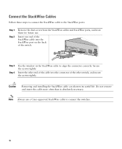
...end of the StackWise cable into the connector of the other end of the cable into the StackWise port on the back of the switch. Caution Removing and installing the StackWise cable can shorten its useful life. Secure the screws tightly. Connect the StackWise Cables Follow these ...Step 2 Remove the dust covers from the StackWise cables and StackWise ports, and store them for future use a Cisco-approved StackWise cable to align the connector correctly. Insert the other switch, and secure the screws tightly. Do not remove and insert the cable more often than is absolutely necessary. Note ...
...end of the StackWise cable into the connector of the other end of the cable into the StackWise port on the back of the switch. Caution Removing and installing the StackWise cable can shorten its useful life. Secure the screws tightly. Connect the StackWise Cables Follow these ...Step 2 Remove the dust covers from the StackWise cables and StackWise ports, and store them for future use a Cisco-approved StackWise cable to align the connector correctly. Insert the other switch, and secure the screws tightly. Do not remove and insert the cable more often than is absolutely necessary. Note ...
Getting Started Guide
Page 19
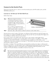
... compliant with IEEE 802.3af, and also provide Cisco pre-standard PoE support for connections to a maximum switch power output of PoE. By default, a Catalyst 3750 switch PoE port automatically provides power when a valid powered device is enabled, the switch detects the required cable type for copper Ethernet connections.../1000 ports Insert the other cable end into an RJ-45 connector on switches running Cisco IOS Release 12.2(18)SE or later. Each of the Catalyst 3750-24PS switch 10/100 ports or the Catalyst 3750G-24PS switch 10/100/1000 ports can deliver up to a copper 10/100, 10...
... compliant with IEEE 802.3af, and also provide Cisco pre-standard PoE support for connections to a maximum switch power output of PoE. By default, a Catalyst 3750 switch PoE port automatically provides power when a valid powered device is enabled, the switch detects the required cable type for copper Ethernet connections.../1000 ports Insert the other cable end into an RJ-45 connector on switches running Cisco IOS Release 12.2(18)SE or later. Each of the Catalyst 3750-24PS switch 10/100 ports or the Catalyst 3750G-24PS switch 10/100/1000 ports can deliver up to a copper 10/100, 10...
Getting Started Guide
Page 20
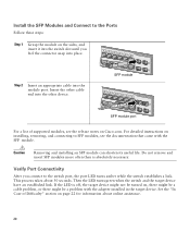
...13 14 13X 15 16 17 18 19 20 21 22 23 24 Catalyst 3750G SERIES PoE-24 23X 25 14X 27 24X 26 28 SFP module ...device. Install the SFP Modules and Connect to the switch port, the port LED turns amber while the switch establishes a link. For detailed instructions on installing, ..., see the release notes on the sides, and insert it into the switch slot until you feel the connector snap into place. Caution Removing and installing... end into the module port. Then the LED turns green when the switch and the target device have an established link. Verify Port Connectivity After ...
...13 14 13X 15 16 17 18 19 20 21 22 23 24 Catalyst 3750G SERIES PoE-24 23X 25 14X 27 24X 26 28 SFP module ...device. Install the SFP Modules and Connect to the switch port, the port LED turns amber while the switch establishes a link. For detailed instructions on installing, ..., see the release notes on the sides, and insert it into the switch slot until you feel the connector snap into place. Caution Removing and installing... end into the module port. Then the LED turns green when the switch and the target device have an established link. Verify Port Connectivity After ...


