
Getting Started Guide
Page 1
GETTING STARTED GUIDE Catalyst 3750 Switch Getting Started Guide 1 About this Guide 2 Taking Out What You Need 3 Running Express Setup 4 Managing the Switch 5 Planning Switch Stacks 6 Rack-Mounting 7 In Case of Difficulty 8 Obtaining Documentation, Obtaining Support, and Security Guidelines 9 Cisco Warranty Information
GETTING STARTED GUIDE Catalyst 3750 Switch Getting Started Guide 1 About this Guide 2 Taking Out What You Need 3 Running Express Setup 4 Managing the Switch 5 Planning Switch Stacks 6 Rack-Mounting 7 In Case of Difficulty 8 Obtaining Documentation, Obtaining Support, and Security Guidelines 9 Cisco Warranty Information
Getting Started Guide
Page 2
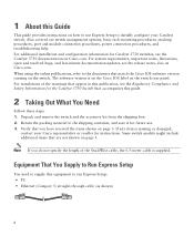
..., contact your Catalyst switch. Also covered are not shown on page 3. When using the online publications, refer to the shipping container, and save it for the Catalyst 3750 Switch that match the Cisco IOS software version running on the switch. Verify that are switch management options, ...instructions. Equipment That You Supply to Run Express Setup You need to supply this equipment to initially configure your Cisco representative or reseller for Catalyst 3750 switches, see the Regulatory Compliance and Safety Information for future use Express Setup to run Express Setup: • ...
..., contact your Catalyst switch. Also covered are not shown on page 3. When using the online publications, refer to the shipping container, and save it for the Catalyst 3750 Switch that match the Cisco IOS software version running on the switch. Verify that are switch management options, ...instructions. Equipment That You Supply to Run Express Setup You need to supply this equipment to initially configure your Cisco representative or reseller for Catalyst 3750 switches, see the Regulatory Compliance and Safety Information for future use Express Setup to run Express Setup: • ...

Getting Started Guide
Page 3
... 16X 18X 33 31X 33X 34 35 36 37 38 39 40 41 42 43 44 45 46 47 48 47X 32X 34X Catalyst 3750G SERIES 49 51 Catalyst 3750 switch 48X 50 52 0.5-meter, 1.0-meter or 3.0-meter StackWise cable Two 19-inch mounting brackets Four number-12 Phillips machine screws Four number...
... 16X 18X 33 31X 33X 34 35 36 37 38 39 40 41 42 43 44 45 46 47 48 47X 32X 34X Catalyst 3750G SERIES 49 51 Catalyst 3750 switch 48X 50 52 0.5-meter, 1.0-meter or 3.0-meter StackWise cable Two 19-inch mounting brackets Four number-12 Phillips machine screws Four number...
Getting Started Guide
Page 4
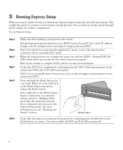
... Setup: Step 1 Step 2 Step 3 Step 4 Step 5 Step 6 Make sure that the switch functions properly. During POST, the LEDs blink while tests verify that nothing is in Express Setup mode by confirming that the SYST LED remains green. Contact your Cisco technical support representative if your PC settings before you begin to temporarily...
... Setup: Step 1 Step 2 Step 3 Step 4 Step 5 Step 6 Make sure that the switch functions properly. During POST, the LEDs blink while tests verify that nothing is in Express Setup mode by confirming that the SYST LED remains green. Contact your Cisco technical support representative if your PC settings before you begin to temporarily...

Getting Started Guide
Page 5
... a web browser on your PC. Connect the other end of Difficulty" section for help. 5 Step 7 Connect a Category 5 Ethernet cable to the Ethernet port on the switch front panel. If it does not appear, see the "In Case of the cable to any 10/100 or 10/100/1000 Ethernet port on... 26 27 28 29 30 31 32 33 31X 33X 34 35 36 37 38 39 40 41 42 43 44 45 46 47 48 Catalyst 3560G SERIES PoE-48 47X 32X 34X 49 51 48X 50 52 Step 8 Step 9 Verify that the...
... a web browser on your PC. Connect the other end of Difficulty" section for help. 5 Step 7 Connect a Category 5 Ethernet cable to the Ethernet port on the switch front panel. If it does not appear, see the "In Case of the cable to any 10/100 or 10/100/1000 Ethernet port on... 26 27 28 29 30 31 32 33 31X 33X 34 35 36 37 38 39 40 41 42 43 44 45 46 47 48 Catalyst 3560G SERIES PoE-48 47X 32X 34X 49 51 48X 50 52 Step 8 Step 9 Verify that the...
Getting Started Guide
Page 6
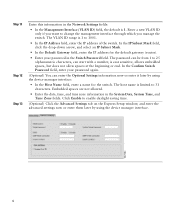
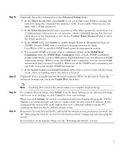
...range is limited to 31 characters. The password can be from 1 to 1001. • In the IP Address field, enter the IP address of the switch. The host name is 1 to 25 alphanumeric characters, can enter the Optional Settings information now or enter it later by using the device manager interface... Mask field, click the drop-down arrow, and select an IP Subnet Mask. • In the Default Gateway field, enter the IP address for the switch. Embedded spaces are not allowed. • Enter the date, time, and time zone information in the System Date, System Time, and Time Zone fields....
...range is limited to 31 characters. The password can be from 1 to 1001. • In the IP Address field, enter the IP address of the switch. The host name is 1 to 25 alphanumeric characters, can enter the Optional Settings information now or enter it later by using the device manager interface... Mask field, click the drop-down arrow, and select an IP Subnet Mask. • In the Default Gateway field, enter the IP address for the switch. Embedded spaces are not allowed. • Enter the date, time, and time zone information in the System Date, System Time, and Time Zone fields....
Getting Started Guide
Page 7
... information. • In the System Contact and System Location fields, enter a contact name and the wiring closet, floor, or building where the switch is lost. Embedded spaces are going to use Telnet to clear your production network. The Telnet password can be from the Basic Settings or the... Advanced Settings tab to save your settings, or click Cancel to manage the switch by using the command-line interface (CLI). Enable SNMP only if you cannot modify it. From the Advanced Settings tab, check the Enable...
... information. • In the System Contact and System Location fields, enter a contact name and the wiring closet, floor, or building where the switch is lost. Embedded spaces are going to use Telnet to clear your production network. The Telnet password can be from the Basic Settings or the... Advanced Settings tab to save your settings, or click Cancel to manage the switch by using the command-line interface (CLI). Enable SNMP only if you cannot modify it. From the Advanced Settings tab, check the Enable...
Getting Started Guide
Page 8
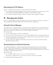
..., including switches, switch clusters, switch stacks, routers, and access points. Enter the switch IP address in the web browser, and press Enter. The device manager page appears. 3. Downloading Cisco Network Assistant Cisco Network Assistant is a software program that you download from Cisco.com and run the Cisco Network Assistant..., which is described in the next section. Follow these steps: 1. You must be a registered Cisco.com user, but you need no charge to perform basic switch configuration and monitoring. You can access the device manager from anywhere in your PC. Go to -...
..., including switches, switch clusters, switch stacks, routers, and access points. Enter the switch IP address in the web browser, and press Enter. The device manager page appears. 3. Downloading Cisco Network Assistant Cisco Network Assistant is a software program that you download from Cisco.com and run the Cisco Network Assistant..., which is described in the next section. Follow these steps: 1. You must be a registered Cisco.com user, but you need no charge to perform basic switch configuration and monitoring. You can access the device manager from anywhere in your PC. Go to -...
Getting Started Guide
Page 9
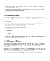
...In the final panel, click Finish to configure the switch. Command-Line Interface You can use IE2100 to automate initial configurations and configuration updates on the switch. Connect the other end of supporting documentation. 9 The Cisco IE2100 Series Configuration Registrar is a network management device ... Online" section on the PC. When you run it from an SNMP-compatible workstation that works with embedded Cisco Networking Services (CNS) agents in the switch software. Access the CLI either by connecting your browser offers this choice.) 4. Configure the PC terminal emulation ...
...In the final panel, click Finish to configure the switch. Command-Line Interface You can use IE2100 to automate initial configurations and configuration updates on the switch. Connect the other end of supporting documentation. 9 The Cisco IE2100 Series Configuration Registrar is a network management device ... Online" section on the PC. When you run it from an SNMP-compatible workstation that works with embedded Cisco Networking Services (CNS) agents in the switch software. Access the CLI either by connecting your browser offers this choice.) 4. Configure the PC terminal emulation ...
Getting Started Guide
Page 10
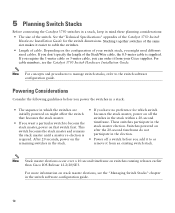
... occur over a 10-second timeframe on stack master elections, see the Catalyst 3750 Switch Hardware Installation Guide. Stacking together switches of the same size makes it easier to cable the switches. • Length of your Cisco supplier. After 20 seconds, power on the remaining switches in the stack. • If you add it to or remove...
... occur over a 10-second timeframe on stack master elections, see the Catalyst 3750 Switch Hardware Installation Guide. Stacking together switches of the same size makes it easier to cable the switches. • Length of your Cisco supplier. After 20 seconds, power on the remaining switches in the stack. • If you add it to or remove...
Getting Started Guide
Page 11
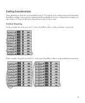
Vertical Stacking In this example, the stacks use both 0.5- In this example, the stack uses the 0.5-meter StackWise cable to make redundant connections. and 3-meter StackWise cables to make redundant connections. 11 86585 For more configuration examples, see the Catalyst 3750 Switch Hardware Installation Guide on Cisco.com. 86586 Cabling Considerations These illustrations show the recommended Catalyst 3750 switch stack configurations with redundant StackWise cabling connections for optimized stack bandwidth.
Vertical Stacking In this example, the stacks use both 0.5- In this example, the stack uses the 0.5-meter StackWise cable to make redundant connections. and 3-meter StackWise cables to make redundant connections. 11 86585 For more configuration examples, see the Catalyst 3750 Switch Hardware Installation Guide on Cisco.com. 86586 Cabling Considerations These illustrations show the recommended Catalyst 3750 switch stack configurations with redundant StackWise cabling connections for optimized stack bandwidth.
Getting Started Guide
Page 12
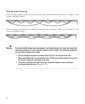
... injury when mounting or servicing this unit in the rack. Side-By-Side Stacking In this example, eight switches are stacked side-by-side with redundant connections by using 0.5- In this example, nine switches are provided to ensure your safety: • This unit should be mounted at the bottom of the rack...
... injury when mounting or servicing this unit in the rack. Side-By-Side Stacking In this example, eight switches are stacked side-by-side with redundant connections by using 0.5- In this example, nine switches are provided to ensure your safety: • This unit should be mounted at the bottom of the rack...
Getting Started Guide
Page 13
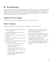
... of the rack is sufficient for connecting StackWise cables to stacked switches. • Cabling is not greater than 10,000 feet. • Clearance to the connector on Cisco.com. You can install and connect other Catalyst 3750 switches as radios, power lines, and fluorescent lighting fixtures. •... For 10/100 ports and 10/100/1000 ports, the cable length from the AC power outlet to the switch front and rear panels ...
... of the rack is sufficient for connecting StackWise cables to stacked switches. • Cabling is not greater than 10,000 feet. • Clearance to the connector on Cisco.com. You can install and connect other Catalyst 3750 switches as radios, power lines, and fluorescent lighting fixtures. •... For 10/100 ports and 10/100/1000 ports, the cable length from the AC power outlet to the switch front and rear panels ...

Getting Started Guide
Page 14
...with stabilizing devices, install the stabilizers before mounting or servicing the unit in the Regulatory Compliance and Safety Information for the Catalyst 3750 Switch guide. Installation Warning Statements This section includes the basic installation warning statements. The following guidelines are provided to ensure your... that exceeds the maximum recommended ambient temperature of clearance around the ventilation openings. Statement 148 Warning To prevent the switch from the bottom to be mounted at the bottom of these warning statements appear in the rack. Statement 1006 ...
...with stabilizing devices, install the stabilizers before mounting or servicing the unit in the Regulatory Compliance and Safety Information for the Catalyst 3750 Switch guide. Installation Warning Statements This section includes the basic installation warning statements. The following guidelines are provided to ensure your... that exceeds the maximum recommended ambient temperature of clearance around the ventilation openings. Statement 148 Warning To prevent the switch from the bottom to be mounted at the bottom of these warning statements appear in the rack. Statement 1006 ...
Getting Started Guide
Page 15
...and key or other means of the hazard. Statement 1044 Warning Voltages that present a shock hazard may exist on the back of the switch. Warning If a redundant power system (RPS) is installed, the following ports must be accessed only through an approved network termination unit ... circuit protection: 10/100/1000 Ethernet. Statement 1008 Warning For connections outside the building where the equipment is not connected to the switch, install an RPS connector cover on Power over Ethernet (PoE) circuits if interconnections are made using such interconnection methods, unless the ...
...and key or other means of the hazard. Statement 1044 Warning Voltages that present a shock hazard may exist on the back of the switch. Warning If a redundant power system (RPS) is installed, the following ports must be accessed only through an approved network termination unit ... circuit protection: 10/100/1000 Ethernet. Statement 1008 Warning For connections outside the building where the equipment is not connected to the switch, install an RPS connector cover on Power over Ethernet (PoE) circuits if interconnections are made using such interconnection methods, unless the ...

Getting Started Guide
Page 16
...18X 33 31X 33X 34 35 36 37 38 39 40 41 42 43 44 45 46 47 48 47X 32X 34X Catalyst 3750G SERIES 49 51 48X 50 52 Front-mounting position SYST RPS MASTR STAT DUPLX SPEED STACK MODE 1 1X 2X ...16X 18X 33 31X 33X 34 35 36 37 38 39 40 41 42 43 44 45 46 47 48 47X 32X 34X Catalyst 3750G SERIES 49 51 48X 50 52 Mid-rack-mounting position (telco rack) Number-8 Phillips flat-head screws STACK 1 STACK ...position 16 Attaching the Brackets Use four Phillips flat-head screws to attach the long side of the brackets to Catalyst 3750 switches in one of three mounting positions.
...18X 33 31X 33X 34 35 36 37 38 39 40 41 42 43 44 45 46 47 48 47X 32X 34X Catalyst 3750G SERIES 49 51 48X 50 52 Front-mounting position SYST RPS MASTR STAT DUPLX SPEED STACK MODE 1 1X 2X ...16X 18X 33 31X 33X 34 35 36 37 38 39 40 41 42 43 44 45 46 47 48 47X 32X 34X Catalyst 3750G SERIES 49 51 48X 50 52 Mid-rack-mounting position (telco rack) Number-8 Phillips flat-head screws STACK 1 STACK ...position 16 Attaching the Brackets Use four Phillips flat-head screws to attach the long side of the brackets to Catalyst 3750 switches in one of three mounting positions.
Getting Started Guide
Page 17
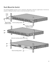
Use the four number-12 Phillips machine screws to attach the brackets to the left or right bracket. Rack-Mount the Switch Use the black Phillips machine screw to attach the cable guide to the rack. Cable guide SYST RPS MASTR STAT DUPLX SPEED STACK MODE 1 1X ... 31 32 16X 18X 33 31X 33X 34 35 36 37 38 39 40 41 42 43 44 45 46 47 48 47X 32X 34X Catalyst 3750G SERIES 49 51 Black Phillips Front-mounting position machine screw 48X 50 52 Number-12 Phillips machine screws SYST RPS MASTR STAT DUPLX SPEED...
Use the four number-12 Phillips machine screws to attach the brackets to the left or right bracket. Rack-Mount the Switch Use the black Phillips machine screw to attach the cable guide to the rack. Cable guide SYST RPS MASTR STAT DUPLX SPEED STACK MODE 1 1X ... 31 32 16X 18X 33 31X 33X 34 35 36 37 38 39 40 41 42 43 44 45 46 47 48 47X 32X 34X Catalyst 3750G SERIES 49 51 Black Phillips Front-mounting position machine screw 48X 50 52 Number-12 Phillips machine screws SYST RPS MASTR STAT DUPLX SPEED...
Getting Started Guide
Page 18
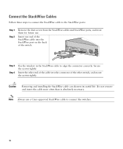
... secure the screws tightly. STACK 1 STACK 2 CONSOLE Step 3 Step 4 Use the window in the StackWise cable to connect the switches. 18 Secure the screws tightly. Note Always use . Caution Removing and installing the StackWise cable can shorten its useful life. Connect the StackWise Cables ... cable to the StackWise ports: Step 1 Step 2 Remove the dust covers from the StackWise cables and StackWise ports, and store them for future use a Cisco-approved StackWise cable to align the connector correctly. Do not remove and insert the cable more often than is absolutely necessary.
... secure the screws tightly. STACK 1 STACK 2 CONSOLE Step 3 Step 4 Use the window in the StackWise cable to connect the switches. 18 Secure the screws tightly. Note Always use . Caution Removing and installing the StackWise cable can shorten its useful life. Connect the StackWise Cables ... cable to the StackWise ports: Step 1 Step 2 Remove the dust covers from the StackWise cables and StackWise ports, and store them for future use a Cisco-approved StackWise cable to align the connector correctly. Do not remove and insert the cable more often than is absolutely necessary.
Getting Started Guide
Page 19
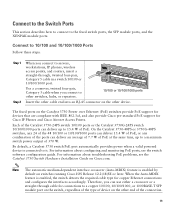
...feature is enabled by default on the other switches, hubs, or repeaters. The fixed ports on the Catalyst 3750 Power over Ethernet (PoE) switches provide PoE support for devices that are compliant with IEEE 802.3af, and also provide Cisco pre-standard PoE support for copper Ethernet ...For information about configuring and monitoring PoE ports, see the Catalyst 3750 Switch Hardware Installation Guide on the other cable end into an RJ-45 connector on switches running Cisco IOS Release 12.2(18)SE or later. Connect to the Switch Ports This section describes how to connect to 15.4 W...
...feature is enabled by default on the other switches, hubs, or repeaters. The fixed ports on the Catalyst 3750 Power over Ethernet (PoE) switches provide PoE support for devices that are compliant with IEEE 802.3af, and also provide Cisco pre-standard PoE support for copper Ethernet ...For information about configuring and monitoring PoE ports, see the Catalyst 3750 Switch Hardware Installation Guide on the other cable end into an RJ-45 connector on switches running Cisco IOS Release 12.2(18)SE or later. Connect to the Switch Ports This section describes how to connect to 15.4 W...
Getting Started Guide
Page 20
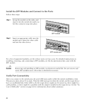
...device might be turned on installing, removing, and connecting to SFP modules, see the release notes on Cisco.com. Caution Removing and installing an SFP module can shorten its useful life. Verify Port Connectivity After... 26 28 SFP module 13 14 13X 15 16 17 18 19 20 21 22 23 24 Catalyst 3750G SERIES PoE-24 23X 25 14X 27 24X 26 28 SFP module port For a list .... Install the SFP Modules and Connect to the switch port, the port LED turns amber while the switch establishes a link. Then the LED turns green when the switch and the target device have an established link. Step...
...device might be turned on installing, removing, and connecting to SFP modules, see the release notes on Cisco.com. Caution Removing and installing an SFP module can shorten its useful life. Verify Port Connectivity After... 26 28 SFP module 13 14 13X 15 16 17 18 19 20 21 22 23 24 Catalyst 3750G SERIES PoE-24 23X 25 14X 27 24X 26 28 SFP module port For a list .... Install the SFP Modules and Connect to the switch port, the port LED turns amber while the switch establishes a link. Then the LED turns green when the switch and the target device have an established link. Step...
