Getting Started Guide
Page 4
... SYST LED turns amber. SYST RPS STAT DUPLX SPEED PoE MODE 1 1X 23 45 67 8 9 10 11 12 13 14 15 16 15X 2X 16X Mode button Verify that the switch is connected to a grounded AC outlet. Contact your Cisco technical support representative if your PC settings before you press... the button, release it begins the power-on self-test (POST). POST errors are green. (On some models, the RPS and PoE LEDs remain off.) 4 This enables the switch to connect to complete POST, ...
... SYST LED turns amber. SYST RPS STAT DUPLX SPEED PoE MODE 1 1X 23 45 67 8 9 10 11 12 13 14 15 16 15X 2X 16X Mode button Verify that the switch is connected to a grounded AC outlet. Contact your Cisco technical support representative if your PC settings before you press... the button, release it begins the power-on self-test (POST). POST errors are green. (On some models, the RPS and PoE LEDs remain off.) 4 This enables the switch to connect to complete POST, ...

Getting Started Guide
Page 5
... 31X 33X 34 35 36 37 38 39 40 41 42 43 44 45 46 47 48 Catalyst 3560G SERIES PoE-48 47X 32X 34X 49 51 48X 50 52 Step 8 Step 9 Verify that the switch and PC Ethernet ports LEDs are green. If it does not appear, see the "In Case of... the cable to any 10/100 or 10/100/1000 Ethernet port on the switch front panel. DHCP-enabled...
... 31X 33X 34 35 36 37 38 39 40 41 42 43 44 45 46 47 48 Catalyst 3560G SERIES PoE-48 47X 32X 34X 49 51 48X 50 52 Step 8 Step 9 Verify that the switch and PC Ethernet ports LEDs are green. If it does not appear, see the "In Case of... the cable to any 10/100 or 10/100/1000 Ethernet port on the switch front panel. DHCP-enabled...
Getting Started Guide
Page 15
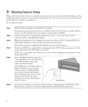
... other means of the hazard. Statement 1008 Warning For connections outside the building where the equipment is not connected to the switch, install an RPS connector cover on Power over Ethernet (PoE) circuits if interconnections are made using uninsulated exposed metal contacts, conductors, or terminals. Avoid using such interconnection methods, unless the... termination unit with integral circuit protection: 10/100/1000 Ethernet. Statement 1044 Warning Voltages that present a shock hazard may exist on the back of the switch.
... other means of the hazard. Statement 1008 Warning For connections outside the building where the equipment is not connected to the switch, install an RPS connector cover on Power over Ethernet (PoE) circuits if interconnections are made using uninsulated exposed metal contacts, conductors, or terminals. Avoid using such interconnection methods, unless the... termination unit with integral circuit protection: 10/100/1000 Ethernet. Statement 1044 Warning Voltages that present a shock hazard may exist on the back of the switch.
Getting Started Guide
Page 19
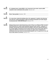
... how to connect to a maximum switch power output of device on the Catalyst 3750 Power over Ethernet (PoE) switches provide PoE support for devices that are compliant with IEEE 802.3af, and also provide Cisco pre-standard PoE support for copper Ethernet connections and configures the interfaces accordingly. By default, a Catalyst 3750 switch PoE port automatically provides power when a valid...
... how to connect to a maximum switch power output of device on the Catalyst 3750 Power over Ethernet (PoE) switches provide PoE support for devices that are compliant with IEEE 802.3af, and also provide Cisco pre-standard PoE support for copper Ethernet connections and configures the interfaces accordingly. By default, a Catalyst 3750 switch PoE port automatically provides power when a valid...
Getting Started Guide
Page 20
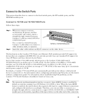
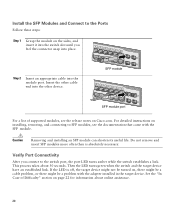
...connector snap into place. This process takes about online assistance. 20 Then the LED turns green when the switch and the target device have an established link. See the "In Case of supported modules, see the ...into the other device. 13 14 13X 15 16 17 18 19 20 21 22 23 24 Catalyst 3750G SERIES PoE-24 23X 25 14X 27 24X 26 28 SFP module 13 14 13X 15 16 17 18...Step 1 Grasp the module on the sides, and insert it into the switch slot until you connect to SFP modules, see the release notes on Cisco.com. Do not remove and insert SFP modules more often than is ...
...connector snap into place. This process takes about online assistance. 20 Then the LED turns green when the switch and the target device have an established link. See the "In Case of supported modules, see the ...into the other device. 13 14 13X 15 16 17 18 19 20 21 22 23 24 Catalyst 3750G SERIES PoE-24 23X 25 14X 27 24X 26 28 SFP module 13 14 13X 15 16 17 18...Step 1 Grasp the module on the sides, and insert it into the switch slot until you connect to SFP modules, see the release notes on Cisco.com. Do not remove and insert SFP modules more often than is ...
