
Hardware Installation Guide
Page 14
...Guide xii 78-15136-02 c. Click Go. The Cisco warranty page appears. Actual delivery times can also contact the Cisco service and support website for Hardware Cisco or its service center will use the product, provided that the fan and power supply warranty is supported for as long ...print the document in which you would like to view the document. Replacement, Repair, or Refund Policy for assistance: http://www.cisco.com/public/Support_root.shtml. Cisco reserves the right to ship a replacement part within ten (10) working days after receipt of the discontinuance. d. You can ...
...Guide xii 78-15136-02 c. Click Go. The Cisco warranty page appears. Actual delivery times can also contact the Cisco service and support website for Hardware Cisco or its service center will use the product, provided that the fan and power supply warranty is supported for as long ...print the document in which you would like to view the document. Replacement, Repair, or Refund Policy for assistance: http://www.cisco.com/public/Support_root.shtml. Cisco reserves the right to ship a replacement part within ten (10) working days after receipt of the discontinuance. d. You can ...

Hardware Installation Guide
Page 49
... System is not powered on the RPS, and the LED should turn green. RPS LED The RPS LED shows the RPS status. Contact Cisco Systems. The internal power supply in a fault condition. System is receiving power but is not functioning properly. RPS is connected but is ...unavailable because it does not, the RPS fan could have failed. System is functioning properly. Table 2-2 lists the LED colors and their meanings. Press the Standby/Active button on . If ...
... System is not powered on the RPS, and the LED should turn green. RPS LED The RPS LED shows the RPS status. Contact Cisco Systems. The internal power supply in a fault condition. System is receiving power but is not functioning properly. RPS is connected but is ...unavailable because it does not, the RPS fan could have failed. System is functioning properly. Table 2-2 lists the LED colors and their meanings. Press the Standby/Active button on . If ...

Hardware Installation Guide
Page 54
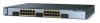
... panels have an AC power connector, an RPS connector, an RJ-45 console port, and two StackWise ports. (See Figure 2-8 and Figure 2-9.) Figure 2-8 Catalyst 3750-24TS, 3750G-24T, 3750G-12S, and 3750-48TS Rear Panel 86548 STACK 1 STACK 2 CONSOLE 1.6A-100R>09A-A2T0,IN05GV0-~60 HZ [email protected] 1 23 4 5 1 StackWise...
... panels have an AC power connector, an RPS connector, an RJ-45 console port, and two StackWise ports. (See Figure 2-8 and Figure 2-9.) Figure 2-8 Catalyst 3750-24TS, 3750G-24T, 3750G-12S, and 3750-48TS Rear Panel 86548 STACK 1 STACK 2 CONSOLE 1.6A-100R>09A-A2T0,IN05GV0-~60 HZ [email protected] 1 23 4 5 1 StackWise...

Hardware Installation Guide
Page 55
... or equipment. Equipment might be damaged if connected to similar Cisco equipment. Chapter 2 Product Overview Figure 2-9 Catalyst 3750G-24TS Rear Panel Rear Panel Description 86547 STACK 1 STACK 2 CONSOLE DSCPIENPCPO+IUWF1TI2EESvDRFISO@NUR1MP7RPAaELNYMUOATLE 1 23 4 5 1 StackWise ports 2 RJ-45 console port 3 Fan exhaust 4 AC power connector 5 RPS connector StackWise Ports The Catalyst 3750 switch ships with...
... or equipment. Equipment might be damaged if connected to similar Cisco equipment. Chapter 2 Product Overview Figure 2-9 Catalyst 3750G-24TS Rear Panel Rear Panel Description 86547 STACK 1 STACK 2 CONSOLE DSCPIENPCPO+IUWF1TI2EESvDRFISO@NUR1MP7RPAaELNYMUOATLE 1 23 4 5 1 StackWise ports 2 RJ-45 console port 3 Fan exhaust 4 AC power connector 5 RPS connector StackWise Ports The Catalyst 3750 switch ships with...
