
Hardware Installation Guide
Page 10
... 3-47 Connecting to 1000BASE-T SFP Modules 3-48 Where to Go Next 3-50 4 C H A P T E R Troubleshooting 4-1 Understanding POST Results 4-1 Clearing the Switch IP Address and Configuration 4-2 Diagnosing Problems 4-3 Replacing a Failed Stack Member 4-7 A A P P E N D I X Technical Specifications A-1 B A P P E N D I X Connector and Cable Specifications B-1 Connector Specifications B-1 10/100/1000 Ports B-1 Connecting to 1000BASE-T Devices B-2 10/100 Ports B-3 SFP Module Ports...
... 3-47 Connecting to 1000BASE-T SFP Modules 3-48 Where to Go Next 3-50 4 C H A P T E R Troubleshooting 4-1 Understanding POST Results 4-1 Clearing the Switch IP Address and Configuration 4-2 Diagnosing Problems 4-3 Replacing a Failed Stack Member 4-7 A A P P E N D I X Technical Specifications A-1 B A P P E N D I X Connector and Cable Specifications B-1 Connector Specifications B-1 10/100/1000 Ports B-1 Connecting to 1000BASE-T Devices B-2 10/100 Ports B-3 SFP Module Ports...

Hardware Installation Guide
Page 12
Contents E A P P E N D I X INDEX Translated Safety Warnings E-1 Attaching the Cisco RPS (model PWR300-AC-RPS-N1) E-1 Attaching the Cisco RPS (model PWR675-AC-RPS-N1) E-2 Installation Warning E-4 Installation Instructions E-5 Jewelry Removal Warning E-6 Stacking the Chassis Warning E-8 Main Disconnecting Device E-10 Grounded Equipment Warning E-11 Installing or Replacing the Unit E-12 Overtemperature Warning E-14 Working During Lightning...
Contents E A P P E N D I X INDEX Translated Safety Warnings E-1 Attaching the Cisco RPS (model PWR300-AC-RPS-N1) E-1 Attaching the Cisco RPS (model PWR675-AC-RPS-N1) E-2 Installation Warning E-4 Installation Instructions E-5 Jewelry Removal Warning E-6 Stacking the Chassis Warning E-8 Main Disconnecting Device E-10 Grounded Equipment Warning E-11 Installing or Replacing the Unit E-12 Overtemperature Warning E-14 Working During Lightning...

Hardware Installation Guide
Page 14
... to five (5) years. Select the language in Adobe Portable Document Format (PDF). Replacement, Repair, or Refund Policy for assistance: http://www.cisco.com/public/Support_root.shtml. d. Actual delivery times can also contact the Cisco service and support website for Hardware Cisco or its exclusive warranty remedy. You can vary, depending on the customer location...
... to five (5) years. Select the language in Adobe Portable Document Format (PDF). Replacement, Repair, or Refund Policy for assistance: http://www.cisco.com/public/Support_root.shtml. d. Actual delivery times can also contact the Cisco service and support website for Hardware Cisco or its exclusive warranty remedy. You can vary, depending on the customer location...

Hardware Installation Guide
Page 47
... SFP module slot. You use Category 5 cable with LC or MT-RJ connectors to connect to a copper SFP module. The Catalyst 3750 models support these Cisco SFP options: • 1000BASE-LX • 1000BASE-SX • 1000BASE-T For more information about these SFP modules, refer to your SFP module documentation. 78-15136...
... SFP module slot. You use Category 5 cable with LC or MT-RJ connectors to connect to a copper SFP module. The Catalyst 3750 models support these Cisco SFP options: • 1000BASE-LX • 1000BASE-SX • 1000BASE-T For more information about these SFP modules, refer to your SFP module documentation. 78-15136...

Hardware Installation Guide
Page 62
... or weld the metal object to power lines, remove jewelry (including rings, necklaces, and watches). Metal objects will heat up when connected to install or replace this equipment. Warning The plug-socket combination must be allowed to power and ground and can cause severe bodily injury and equipment damage. Warning Before...
... or weld the metal object to power lines, remove jewelry (including rings, necklaces, and watches). Metal objects will heat up when connected to install or replace this equipment. Warning The plug-socket combination must be allowed to power and ground and can cause severe bodily injury and equipment damage. Warning Before...

Hardware Installation Guide
Page 63
... the system or connect or disconnect cables during normal use. Warning This equipment is connected to all national laws and regulations. Warning Attach only the Cisco RPS (model PWR675-AC-RPS-N1) to the laser beam. 78-15136-02 Catalyst 3750 Switch Hardware Installation Guide 3-3 Warning Class 1 laser product Warning Avoid... exposure to the RPS receptacle. To prevent airflow restriction, allow at least 3 inches (7.6 cm) of lightning activity. Warning When installing or replacing the unit, the ground connection must always be grounded.
... the system or connect or disconnect cables during normal use. Warning This equipment is connected to all national laws and regulations. Warning Attach only the Cisco RPS (model PWR675-AC-RPS-N1) to the laser beam. 78-15136-02 Catalyst 3750 Switch Hardware Installation Guide 3-3 Warning Class 1 laser product Warning Avoid... exposure to the RPS receptacle. To prevent airflow restriction, allow at least 3 inches (7.6 cm) of lightning activity. Warning When installing or replacing the unit, the ground connection must always be grounded.

Hardware Installation Guide
Page 65
... properly according to the Hungarian EMC Class A requirements (MSZEN55022). Class A Notice for industrial use type. If this . Class A equipment is a class A product and should be replaced with a residential-use . Statement 256 78-15136-02 Catalyst 3750 Switch Hardware Installation Guide 3-5 The seller or buyer should be used .
... properly according to the Hungarian EMC Class A requirements (MSZEN55022). Class A Notice for industrial use type. If this . Class A equipment is a class A product and should be replaced with a residential-use . Statement 256 78-15136-02 Catalyst 3750 Switch Hardware Installation Guide 3-5 The seller or buyer should be used .

Hardware Installation Guide
Page 97
...and secure the screws tightly. Insert the other end of the switch. Chapter 3 Switch Installation Connecting StackWise Cable to StackWise Ports To use a Cisco-approved StackWise cable to connect the switches. Step 3 Step 4 Use the window in the StackWise cable to the switch software configuration guide or the... switch command reference. Note When the connectors are not being used, replace the dust covers on them to protect them from the StackWise cables and StackWise ports, and store them for future use CMS, go...
...and secure the screws tightly. Insert the other end of the switch. Chapter 3 Switch Installation Connecting StackWise Cable to StackWise Ports To use a Cisco-approved StackWise cable to connect the switches. Step 3 Step 4 Use the window in the StackWise cable to the switch software configuration guide or the... switch command reference. Note When the connectors are not being used, replace the dust covers on them to protect them from the StackWise cables and StackWise ports, and store them for future use CMS, go...

Hardware Installation Guide
Page 100
... can use any combination of the Catalyst 3750 switches. Each port must not exceed the stipulated cable length for reliable communications. These field-replaceable modules provide uplink interfaces. See the "Installation Guidelines" section on the other end of the cable, and the cable must match the ... the requirements for the switch. 3-40 Catalyst 3750 Switch Hardware Installation Guide 78-15136-02 Refer to the Catalyst 3750 release notes for Cisco to install and remove SFP modules. Each SFP module has an internal serial EEPROM that the Catalyst 3750 switch supports. SFP modules are ...
... can use any combination of the Catalyst 3750 switches. Each port must not exceed the stipulated cable length for reliable communications. These field-replaceable modules provide uplink interfaces. See the "Installation Guidelines" section on the other end of the cable, and the cable must match the ... the requirements for the switch. 3-40 Catalyst 3750 Switch Hardware Installation Guide 78-15136-02 Refer to the Catalyst 3750 release notes for Cisco to install and remove SFP modules. Each SFP module has an internal serial EEPROM that the Catalyst 3750 switch supports. SFP modules are ...

Hardware Installation Guide
Page 102
...-15136-02 Installing and Removing SFP Modules Chapter 3 Switch Installation Note On some SFP modules, the send and receive (TX and RX) markings might be replaced by arrows that show the direction of the slot opening.
...-15136-02 Installing and Removing SFP Modules Chapter 3 Switch Installation Note On some SFP modules, the send and receive (TX and RX) markings might be replaced by arrows that show the direction of the slot opening.

Hardware Installation Guide
Page 111
...They show failures in the power-on , it begins POST, a series of the switch LEDs, see the "LEDs" section on Cisco.com, or the documentation that came with your SNMP application for 2 seconds. 78-15136-02 Catalyst 3750 Switch Hardware Installation Guide 4-1 ... amber for troubleshooting problems: • Understanding POST Results, page 4-1 • Clearing the Switch IP Address and Configuration, page 4-2 • Replacing a Failed Stack Member, page 4-7 Understanding POST Results As the switch powers on self-test (POST), port-connectivity problems, and overall switch performance...
...They show failures in the power-on , it begins POST, a series of the switch LEDs, see the "LEDs" section on Cisco.com, or the documentation that came with your SNMP application for 2 seconds. 78-15136-02 Catalyst 3750 Switch Hardware Installation Guide 4-1 ... amber for troubleshooting problems: • Understanding POST Results, page 4-1 • Clearing the Switch IP Address and Configuration, page 4-2 • Replacing a Failed Stack Member, page 4-7 Understanding POST Results As the switch powers on self-test (POST), port-connectivity problems, and overall switch performance...
Hardware Installation Guide
Page 115
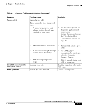
...• The cable is wired incorrectly. • A crossover or straight-through was required, or vice-versa. Fatal POST error detected. • Replace with a tested good cable. • For 1000BASE-T connections, be sure to use a twisted four-pair, Category 5 cable. • Wait 30... seconds for possible loops. Contact Cisco Systems. 78-15136-02 Catalyst 3750 Switch Hardware Installation Guide 4-5 Incorrect baud rate. Reset the emulation software to turn green. Resolution •...
...• The cable is wired incorrectly. • A crossover or straight-through was required, or vice-versa. Fatal POST error detected. • Replace with a tested good cable. • For 1000BASE-T connections, be sure to use a twisted four-pair, Category 5 cable. • Wait 30... seconds for possible loops. Contact Cisco Systems. 78-15136-02 Catalyst 3750 Switch Hardware Installation Guide 4-5 Incorrect baud rate. Reset the emulation software to turn green. Resolution •...

Hardware Installation Guide
Page 116
...the SFP module. Remove the StackWise cable, and inspect the cable and StackWise port for physical damage to recover from the switch, and replace it with a known good cable. Secure the thumb screws on the errdisable recovery command. If the StackWise cable is not installed upside...down . Bad StackWise cable or damaged StackWise port. Verify that the SFP module is bad, replace it with a known good SFP module. See Figure 3-35. Replace the SFP module with a Cisco-approved module. Catalyst 3750 Switch Hardware Installation Guide 4-6 78-15136-02 Resolution Remove the SFP ...
...the SFP module. Remove the StackWise cable, and inspect the cable and StackWise port for physical damage to recover from the switch, and replace it with a known good cable. Secure the thumb screws on the errdisable recovery command. If the StackWise cable is not installed upside...down . Bad StackWise cable or damaged StackWise port. Verify that the SFP module is bad, replace it with a known good SFP module. See Figure 3-35. Replace the SFP module with a Cisco-approved module. Catalyst 3750 Switch Hardware Installation Guide 4-6 78-15136-02 Resolution Remove the SFP ...
Hardware Installation Guide
Page 117
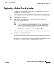
... failed switch. To assign the member number manually, refer to the stack. The replacement switch will have the same configuration for any members in the stack, you need to replace a failed stack member, you had manually set the member numbers for all the interfaces... Guide 4-7 Chapter 4 Troubleshooting Replacing a Failed Stack Member Replacing a Failed Stack Member If you need to manually assign the replacement switch the same member number as the failed switch. Make sure the replacement switch is powered off, and then connect the replacement switch to the switch software ...
... failed switch. To assign the member number manually, refer to the stack. The replacement switch will have the same configuration for any members in the stack, you need to replace a failed stack member, you had manually set the member numbers for all the interfaces... Guide 4-7 Chapter 4 Troubleshooting Replacing a Failed Stack Member Replacing a Failed Stack Member If you need to manually assign the replacement switch the same member number as the failed switch. Make sure the replacement switch is powered off, and then connect the replacement switch to the switch software ...

Hardware Installation Guide
Page 118
Replacing a Failed Stack Member Chapter 4 Troubleshooting Catalyst 3750 Switch Hardware Installation Guide 4-8 78-15136-02
Replacing a Failed Stack Member Chapter 4 Troubleshooting Catalyst 3750 Switch Hardware Installation Guide 4-8 78-15136-02

Hardware Installation Guide
Page 194
... stacking the switches See also stacking starting the terminal emulation software D-9 table or shelf-mounting 3-36 wall mounting 3-32 warning E-5 See also procedures installing or replacing the unit warning E-12 installing SFP modules 3-41 to 3-43 IOS command-line interface 2-18 IP address configuring by using Express Setup 1-9 verifying 1-10 to...
... stacking the switches See also stacking starting the terminal emulation software D-9 table or shelf-mounting 3-36 wall mounting 3-32 warning E-5 See also procedures installing or replacing the unit warning E-12 installing SFP modules 3-41 to 3-43 IOS command-line interface 2-18 IP address configuring by using Express Setup 1-9 verifying 1-10 to...

