Hardware Installation Guide
Page 3
... Module LEDs 1-16 USB Mini-Type B Port 1-17 Rear Panel Description 1-17 RJ-45 Console Port LED 1-18 USB Type A Interface 1-18 StackWise Ports 1-19 Power Supply Modules 1-19 Switch Power Supply Modules 1-19 OL-19593-02 Catalyst 3750-X and 3560-X Switch Hardware Installation Guide iii
... Module LEDs 1-16 USB Mini-Type B Port 1-17 Rear Panel Description 1-17 RJ-45 Console Port LED 1-18 USB Type A Interface 1-18 StackWise Ports 1-19 Power Supply Modules 1-19 Switch Power Supply Modules 1-19 OL-19593-02 Catalyst 3750-X and 3560-X Switch Hardware Installation Guide iii
Hardware Installation Guide
Page 5
... Connections 2-27 Where to Go Next 2-29 Power Supply and Fan Module Installation 3-1 Power Supply Module Overview 3-1 Installation Guidelines 3-5 Installing an AC Power Supply 3-7 Installing a DC Power Supply 3-8 Equipment That You Need 3-8 Grounding the Switch 3-9 Installing the DC Power Supply in the Switch 3-11 Wiring the DC Input Power Source 3-11 Finding the Power Supply Module Serial Number 3-12 Fan Module Overview 3-14...
... Connections 2-27 Where to Go Next 2-29 Power Supply and Fan Module Installation 3-1 Power Supply Module Overview 3-1 Installation Guidelines 3-5 Installing an AC Power Supply 3-7 Installing a DC Power Supply 3-8 Equipment That You Need 3-8 Grounding the Switch 3-9 Installing the DC Power Supply in the Switch 3-11 Wiring the DC Input Power Source 3-11 Finding the Power Supply Module Serial Number 3-12 Fan Module Overview 3-14...
Hardware Installation Guide
Page 6
...the Switch Serial Number 4-6 Replacing a Failed Data Stack Member (Catalyst 3750-X Switches) 4-6 Technical Specifications A-1 Switch Specifications A-1 Power Supply Module Specifications A-2 Fan Module Specifications A-4 Connector and Cable Specifications B-1 Connector Specifications B-1 10/100/1000 Ports B-1 10 Gigabit Ethernet...Port C-2 USB Console Port C-2 Installing the Cisco Microsoft Windows USB Device Driver C-3 Installing the Cisco Microsoft Windows XP USB Driver C-4 Installing the Cisco Microsoft Windows 2000 USB Driver C-4 Installing the Cisco Microsoft Windows Vista and Windows 7 USB ...
...the Switch Serial Number 4-6 Replacing a Failed Data Stack Member (Catalyst 3750-X Switches) 4-6 Technical Specifications A-1 Switch Specifications A-1 Power Supply Module Specifications A-2 Fan Module Specifications A-4 Connector and Cable Specifications B-1 Connector Specifications B-1 10/100/1000 Ports B-1 10 Gigabit Ethernet...Port C-2 USB Console Port C-2 Installing the Cisco Microsoft Windows USB Device Driver C-3 Installing the Cisco Microsoft Windows XP USB Driver C-4 Installing the Cisco Microsoft Windows 2000 USB Driver C-4 Installing the Cisco Microsoft Windows Vista and Windows 7 USB ...
Hardware Installation Guide
Page 9
...://www.cisco.com/en/US/products/ps10744/tsd_products_support_series_home.html • Catalyst 3750-X and 3560-X Switch Getting Started Guide • Catalyst 3750-X and 3560-X Switch Hardware Installation Guide • Regulatory Compliance and Safety Information for the Catalyst 3750-X and 3560-X Switch • Installation Notes for the Catalyst 3750-X, Catalyst 3560-X Switch Power Supply Modules...
...://www.cisco.com/en/US/products/ps10744/tsd_products_support_series_home.html • Catalyst 3750-X and 3560-X Switch Getting Started Guide • Catalyst 3750-X and 3560-X Switch Hardware Installation Guide • Regulatory Compliance and Safety Information for the Catalyst 3750-X and 3560-X Switch • Installation Notes for the Catalyst 3750-X, Catalyst 3560-X Switch Power Supply Modules...
Hardware Installation Guide
Page 11
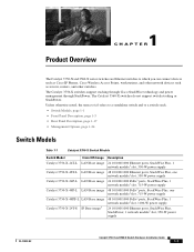
... Cisco IOS Image Catalyst 3750-X-24T-L LAN Base image Catalyst 3750-X-48T-L LAN Base image Catalyst 3750-X-24P-L LAN Base image Catalyst 3750-X-48P-L LAN Base image Catalyst 3750-X-48PF-L LAN Base image Catalyst 3750-X-24T-S IP Base image3 Description 24 10/100/1000 Ethernet ports, StackWise Plus, 1 network module1 slot, 350-W power supply...
... Cisco IOS Image Catalyst 3750-X-24T-L LAN Base image Catalyst 3750-X-48T-L LAN Base image Catalyst 3750-X-24P-L LAN Base image Catalyst 3750-X-48P-L LAN Base image Catalyst 3750-X-48PF-L LAN Base image Catalyst 3750-X-24T-S IP Base image3 Description 24 10/100/1000 Ethernet ports, StackWise Plus, 1 network module1 slot, 350-W power supply...
Hardware Installation Guide
Page 12
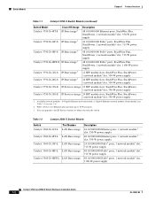
... Overview Table 1-1 Catalyst 3750-X Switch Models (continued) Switch Model Cisco IOS Image Catalyst 3750-X-48T-S IP Base image3 Catalyst 3750-X-24P-S IP Base image3 Catalyst 3750-X-48P-S IP Base image3 Catalyst 3750-X-48PF-S IP Base image3 Catalyst 3750-X-12S-S IP Base image3 Catalyst 3750... Base image Catalyst 3560-X-48PF-L LAN Base image Description 24 10/100/1000 Ethernet ports, 1 network module1 slot, 350-W power supply 48 10/100/1000 Ethernet ports, 1 network module1 slot, 350-W power supply 24 10/100/1000 PoE+2 ports, 1 network module1 slot, 715-W power supply 48 10/100/1000 PoE...
... Overview Table 1-1 Catalyst 3750-X Switch Models (continued) Switch Model Cisco IOS Image Catalyst 3750-X-48T-S IP Base image3 Catalyst 3750-X-24P-S IP Base image3 Catalyst 3750-X-48P-S IP Base image3 Catalyst 3750-X-48PF-S IP Base image3 Catalyst 3750-X-12S-S IP Base image3 Catalyst 3750... Base image Catalyst 3560-X-48PF-L LAN Base image Description 24 10/100/1000 Ethernet ports, 1 network module1 slot, 350-W power supply 48 10/100/1000 Ethernet ports, 1 network module1 slot, 350-W power supply 24 10/100/1000 PoE+2 ports, 1 network module1 slot, 715-W power supply 48 10/100/1000 PoE...
Hardware Installation Guide
Page 13
...IP Base image3 Catalyst 3560-X-48PF-S IP Base image3 Description 24 10/100/1000 Ethernet ports, 1 network module1 slot, 350-W power supply 48 10/100/1000 Ethernet ports, 1 network module1 slot, 350-W power supply 24 10/100/1000 PoE+2 ports, 1 network module1 slot, 715-W power supply 48 10/100/1000 PoE...+2 ports, 1 network module1 slot, 715-W power supply 48 10/100/1000 PoE+2 ports, 1...
...IP Base image3 Catalyst 3560-X-48PF-S IP Base image3 Description 24 10/100/1000 Ethernet ports, 1 network module1 slot, 350-W power supply 48 10/100/1000 Ethernet ports, 1 network module1 slot, 350-W power supply 24 10/100/1000 PoE+2 ports, 1 network module1 slot, 715-W power supply 48 10/100/1000 PoE...+2 ports, 1 network module1 slot, 715-W power supply 48 10/100/1000 PoE+2 ports, 1...

Hardware Installation Guide
Page 15
... the switch without a network module is available. See Table 1-17 for the power supply matrix that provides uplink ports to connect to 30 W) • Support for Cisco enhanced PoE • Support for prestandard Cisco powered devices • Configuration for Cisco intelligent power management, including enhanced power negotiation, power reservation, and per IEC 60950-1. Chapter 1 Product Overview Front Panel Description...
... the switch without a network module is available. See Table 1-17 for the power supply matrix that provides uplink ports to connect to 30 W) • Support for Cisco enhanced PoE • Support for prestandard Cisco powered devices • Configuration for Cisco intelligent power management, including enhanced power negotiation, power reservation, and per IEC 60950-1. Chapter 1 Product Overview Front Panel Description...

Hardware Installation Guide
Page 20
... self-test (POST). For information on the System LED colors during power-on self-test (POST), see the "Diagnosing Problems" section on . There is a fault with PoE+ ports. 6 USB console port LED 7 S-PWR (StackPower) LED2 8... 9 10 1 System LED 2 XPS1 LED 3 Status LED 4 Speed LED 5 Duplex LED 1. XPS = Expandable power system. 2. Only switches with one of the following: • Network module (non-traffic-related) • Power supply • Fan module System is receiving power but is not powered on page 4-1. 1-10 Catalyst 3750-X and 3560-X Switch Hardware Installation Guide OL-19593...
... self-test (POST). For information on the System LED colors during power-on self-test (POST), see the "Diagnosing Problems" section on . There is a fault with PoE+ ports. 6 USB console port LED 7 S-PWR (StackPower) LED2 8... 9 10 1 System LED 2 XPS1 LED 3 Status LED 4 Speed LED 5 Duplex LED 1. XPS = Expandable power system. 2. Only switches with one of the following: • Network module (non-traffic-related) • Power supply • Fan module System is receiving power but is not powered on page 4-1. 1-10 Catalyst 3750-X and 3560-X Switch Hardware Installation Guide OL-19593...
Hardware Installation Guide
Page 21
...See the "Stack LED (Catalyst 3750-X)" section on Cisco.com. Only Catalyst 3750-X switches. 2. These port LEDs, as a group or individually, display information about the switch and about the standby mode and fault conditions. The power supply in StackPower mode (Catalyst 3750-X). To select or ...change . For information about the XPS 2200, see the Cisco eXpandable Power System 2200 Hardware Installation Guide on page 1-14. Table 1-8 lists the...
...See the "Stack LED (Catalyst 3750-X)" section on Cisco.com. Only Catalyst 3750-X switches. 2. These port LEDs, as a group or individually, display information about the switch and about the standby mode and fault conditions. The power supply in StackPower mode (Catalyst 3750-X). To select or ...change . For information about the XPS 2200, see the Cisco eXpandable Power System 2200 Hardware Installation Guide on page 1-14. Table 1-8 lists the...

Hardware Installation Guide
Page 27
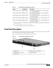
...(only Catalyst 3750-X switches), two fan modules, an XPS 2200 connector, a StackPower connector (only Catalyst 3750-X switches), and two power supply module slots. Figure 1-8 shows the Catalyst 3560-X switch rear panel, which has one connector for either a StackPower or an XPS ...cable connectors 7 Reset button 8 Fan modules 9 StackPower or XPS 2200 connector 10 StackPower connector 11 Power supply modules (AC power supply modules shown) 12 AC power (input) status LED 13 Power supply (output) status LED OL-19593-02 Catalyst 3750-X and 3560-X Switch Hardware Installation Guide 1-17 ...
...(only Catalyst 3750-X switches), two fan modules, an XPS 2200 connector, a StackPower connector (only Catalyst 3750-X switches), and two power supply module slots. Figure 1-8 shows the Catalyst 3560-X switch rear panel, which has one connector for either a StackPower or an XPS ...cable connectors 7 Reset button 8 Fan modules 9 StackPower or XPS 2200 connector 10 StackPower connector 11 Power supply modules (AC power supply modules shown) 12 AC power (input) status LED 13 Power supply (output) status LED OL-19593-02 Catalyst 3750-X and 3560-X Switch Hardware Installation Guide 1-17 ...
Hardware Installation Guide
Page 28
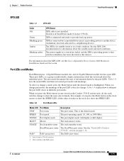
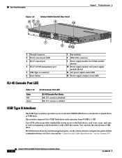
...232 console is disabled. For information about the switch management ports, see the switch software configuration guide and the command reference on Cisco.com and the "Connector and Cable Specifications" section on page B-1. 1-18 Catalyst 3750-X and 3560-X Switch Hardware Installation Guide OL... 5 USB Type A connector 6 Reset button 7 Fan modules 8 XPS 2200 connector 9 Power supply module slot (blank module shown) 10 Power supply module (AC power supply module shown) 11 AC power (input) status LED 12 Power supply (output) status LED RJ-45 Console Port LED Table 1-15 Color Off Green RJ-45...
...232 console is disabled. For information about the switch management ports, see the switch software configuration guide and the command reference on Cisco.com and the "Connector and Cable Specifications" section on page B-1. 1-18 Catalyst 3750-X and 3560-X Switch Hardware Installation Guide OL... 5 USB Type A connector 6 Reset button 7 Fan modules 8 XPS 2200 connector 9 Power supply module slot (blank module shown) 10 Power supply module (AC power supply module shown) 11 AC power (input) status LED 12 Power supply (output) status LED RJ-45 Console Port LED Table 1-15 Color Off Green RJ-45...
Hardware Installation Guide
Page 29
... AC modules, two DC modules, a mixed configuration of one AC and one DC power supply module, or one or two internal power supply modules. Each AC power supply module has a power cord for connection to similar Cisco equipment. The 1100-W and 715-W modules use to nonapproved Cisco cables or equipment. The switch can order these StackWise cables from your...
... AC modules, two DC modules, a mixed configuration of one AC and one DC power supply module, or one or two internal power supply modules. Each AC power supply module has a power cord for connection to similar Cisco equipment. The 1100-W and 715-W modules use to nonapproved Cisco cables or equipment. The switch can order these StackWise cables from your...

Hardware Installation Guide
Page 30
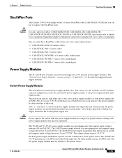
... must use the CAB-3KX-250VAC-JP power cord with one 715-W power supply or (2) 1100-W power supplies Note A 48-port switch with the 1100-W power supply module. Power output to power other devices. Table 1-16 Switch Power Supply Modules Power Supply Module C3KX-PWR-1100WAC=2 48-Port PoE...Port Switch PoE (up to 15.4 W per port) (1) 1100-W power supply 48-Port Switch (1) 1100-W power supply (1) 1100-W power supply plus one 715-W power supply provides up to 30 W per port) (1) 715-W power supply (2) 440-W DC power supplies PoE+ (up to 8.7 W of PoE to all ports. Output...
... must use the CAB-3KX-250VAC-JP power cord with one 715-W power supply or (2) 1100-W power supplies Note A 48-port switch with the 1100-W power supply module. Power output to power other devices. Table 1-16 Switch Power Supply Modules Power Supply Module C3KX-PWR-1100WAC=2 48-Port PoE...Port Switch PoE (up to 15.4 W per port) (1) 1100-W power supply 48-Port Switch (1) 1100-W power supply (1) 1100-W power supply plus one 715-W power supply provides up to 30 W per port) (1) 715-W power supply (2) 440-W DC power supplies PoE+ (up to 8.7 W of PoE to all ports. Output...
Hardware Installation Guide
Page 31
... depending on at a time. Statement 387 The Cisco XPS 2200 is a expandable power system that can support nine network switches and provides power to switch active. PS OK Off Green Red Description Output is disabled, or input is outside operating range (DC LED is on the power supply configuration. When the fan modules are operating...
... depending on at a time. Statement 387 The Cisco XPS 2200 is a expandable power system that can support nine network switches and provides power to switch active. PS OK Off Green Red Description Output is disabled, or input is outside operating range (DC LED is on the power supply configuration. When the fan modules are operating...

Hardware Installation Guide
Page 32
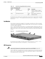
..., failure, and exception history For information about connecting StackPower cables and StackPower guidelines, see the Cisco eXpandable Power System 2200 Hardware Installation Guide on Cisco.com: http://www.cisco.com/go/xps2200_hw See the switch software configuration guide on the installed power supply modules. Rear Panel Description Chapter 1 Product Overview Use the XPS 2200 only with...
..., failure, and exception history For information about connecting StackPower cables and StackPower guidelines, see the Cisco eXpandable Power System 2200 Hardware Installation Guide on Cisco.com: http://www.cisco.com/go/xps2200_hw See the switch software configuration guide on the installed power supply modules. Rear Panel Description Chapter 1 Product Overview Use the XPS 2200 only with...

Hardware Installation Guide
Page 36
...is disrupted. You need to be allowed to de-energize the unit. Statement 1025 Warning This unit might have more than one power supply connection. To prevent airflow restriction, allow at least 3 inches (7.6 cm) of lightning activity. Statement 17B Warning Before working on ...USA, this equipment. A restricted access area can cause severe bodily injury and equipment damage. After power is restored, you might have to reset or reconfigure equipment to regain access to power lines, remove jewelry (including rings, necklaces, and watches). Statement 171 Warning Voice over IP (...
...is disrupted. You need to be allowed to de-energize the unit. Statement 1025 Warning This unit might have more than one power supply connection. To prevent airflow restriction, allow at least 3 inches (7.6 cm) of lightning activity. Statement 17B Warning Before working on ...USA, this equipment. A restricted access area can cause severe bodily injury and equipment damage. After power is restored, you might have to reset or reconfigure equipment to regain access to power lines, remove jewelry (including rings, necklaces, and watches). Statement 171 Warning Voice over IP (...

Hardware Installation Guide
Page 37
... side of the equipment must be easily read. - OL-19593-02 Catalyst 3750-X and 3560-X Switch Hardware Installation Guide 2-3 AC power cord can be connected through an approved network termination unit with the Telcordia GR-1089 NEBS standard, PoE or non-PoE 10/100... radius and connector length is installed, the following ports must comply with the optional 1100-W power-supply module (C3KX-PWR-1100WAC=), first rack-mount the switch before installing the power-supply module. • Make sure power-supply modules and fan modules are met: • Clearance to the nearest rack metal.
... side of the equipment must be easily read. - OL-19593-02 Catalyst 3750-X and 3560-X Switch Hardware Installation Guide 2-3 AC power cord can be connected through an approved network termination unit with the Telcordia GR-1089 NEBS standard, PoE or non-PoE 10/100... radius and connector length is installed, the following ports must comply with the optional 1100-W power-supply module (C3KX-PWR-1100WAC=), first rack-mount the switch before installing the power-supply module. • Make sure power-supply modules and fan modules are met: • Clearance to the nearest rack metal.
Hardware Installation Guide
Page 38
...ports, cable lengths from the switch to connected devices can be greater than normal room temperature. • Cisco Ethernet Switches are equipped with the DC power supply) - However, these fans and blowers can draw dust and other particles, causing contaminant buildup inside the ... a Switch Data Stack (Catalyst 3750-X Switches) Chapter 2 Switch Installation • When connecting or disconnecting the power cord on a switch that is installed above or below a 1100-W power supply-equipped switch, you need a ratcheting torque screwdriver capable of 5 lbf-in. (80 ozf-in system malfunction...
...ports, cable lengths from the switch to connected devices can be greater than normal room temperature. • Cisco Ethernet Switches are equipped with the DC power supply) - However, these fans and blowers can draw dust and other particles, causing contaminant buildup inside the ... a Switch Data Stack (Catalyst 3750-X Switches) Chapter 2 Switch Installation • When connecting or disconnecting the power cord on a switch that is installed above or below a 1100-W power supply-equipped switch, you need a ratcheting torque screwdriver capable of 5 lbf-in. (80 ozf-in system malfunction...
Hardware Installation Guide
Page 39
... vertical rack or on the configurations that you have the optional 1100-W power-supply module, first mount the switch before installing the power-supply module. - Depending on a table. For cable part numbers, see the "StackWise Ports" section on Cisco.com. . In this recommended sequence of events: - For switch dimensions...the switches. Connect the XPS cable to the first switch above the XPS 2200. Stacking switches with the same power-supply modules together makes it from your Cisco supplier. Connect the stack cables to the XPS 2200. - If you do not specify the length of a ...
... vertical rack or on the configurations that you have the optional 1100-W power-supply module, first mount the switch before installing the power-supply module. - Depending on a table. For cable part numbers, see the "StackWise Ports" section on Cisco.com. . In this recommended sequence of events: - For switch dimensions...the switches. Connect the XPS cable to the first switch above the XPS 2200. Stacking switches with the same power-supply modules together makes it from your Cisco supplier. Connect the stack cables to the XPS 2200. - If you do not specify the length of a ...


