Hardware Installation Guide
Page 3
... vii Obtaining Documentation and Submitting a Service Request viii Product Overview 1-1 Switch Models 1-1 Front Panel Description 1-3 SFP Module Slots 1-4 10/100/1000 Ethernet Ports 1-4 PoE+ Ports 1-5 Network Modules 1-5 SFP and SFP+ Modules 1-7 LEDs 1-9 System LED 1-10 XPS LED 1-11 Port LEDs and Modes 1-11 USB Console LED 1-...13 S-PWR LED (Catalyst 3750-X) 1-14 Master LED (Catalyst 3750-X) 1-14 Stack LED (Catalyst 3750-X) 1-14 PoE+ LED 1-15 Network Module LEDs 1-16 USB Mini-Type B Port 1-17 Rear Panel Description 1-17 RJ-45 Console Port LED 1-18 USB Type A ...
... vii Obtaining Documentation and Submitting a Service Request viii Product Overview 1-1 Switch Models 1-1 Front Panel Description 1-3 SFP Module Slots 1-4 10/100/1000 Ethernet Ports 1-4 PoE+ Ports 1-5 Network Modules 1-5 SFP and SFP+ Modules 1-7 LEDs 1-9 System LED 1-10 XPS LED 1-11 Port LEDs and Modes 1-11 USB Console LED 1-...13 S-PWR LED (Catalyst 3750-X) 1-14 Master LED (Catalyst 3750-X) 1-14 Stack LED (Catalyst 3750-X) 1-14 PoE+ LED 1-15 Network Module LEDs 1-16 USB Mini-Type B Port 1-17 Rear Panel Description 1-17 RJ-45 Console Port LED 1-18 USB Type A ...
Hardware Installation Guide
Page 5
... Module 2-25 Removing an SFP Module 2-26 Connecting Devices to the Ethernet Ports 2-26 10/100/1000 Ethernet Port Connections 2-27 PoE+ Port Connections 2-27 Where to Go Next 2-29 Power Supply and Fan Module Installation 3-1 Power Supply Module Overview 3-1 Installation Guidelines... 4-1 Switch LEDs 4-1 Switch Connections 4-2 Bad or Damaged Cable 4-2 Ethernet and Fiber Cables 4-2 Link Status 4-2 10/100/1000 Port Connections 4-3 PoE Port Connections 4-3 SFP Modules 4-3 Interface Settings 4-4 Ping End Device 4-4 Spanning Tree Loops 4-4 Contents OL-19593-02 Catalyst 3750-X and 3560-X Switch Hardware ...
... Module 2-25 Removing an SFP Module 2-26 Connecting Devices to the Ethernet Ports 2-26 10/100/1000 Ethernet Port Connections 2-27 PoE+ Port Connections 2-27 Where to Go Next 2-29 Power Supply and Fan Module Installation 3-1 Power Supply Module Overview 3-1 Installation Guidelines... 4-1 Switch LEDs 4-1 Switch Connections 4-2 Bad or Damaged Cable 4-2 Ethernet and Fiber Cables 4-2 Link Status 4-2 10/100/1000 Port Connections 4-3 PoE Port Connections 4-3 SFP Modules 4-3 Interface Settings 4-4 Ping End Device 4-4 Spanning Tree Loops 4-4 Contents OL-19593-02 Catalyst 3750-X and 3560-X Switch Hardware ...
Hardware Installation Guide
Page 11
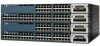
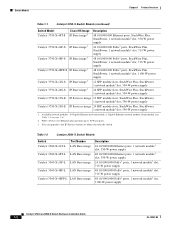
...17 • Management Options, page 1-24 Switch Models Table 1-1 Catalyst 3750-X Switch Models Switch Model Cisco IOS Image Catalyst 3750-X-24T-L LAN Base image Catalyst 3750-X-48T-L LAN Base image Catalyst 3750-X-24P-L... LAN Base image Catalyst 3750-X-48P-L LAN Base image Catalyst 3750-X-48PF-L LAN Base image Catalyst 3750-X-24T-S IP Base image3 Description 24 10/100/1000 ...slot, 350-W power supply 24 10/100/1000 PoE+2 ports, StackWise Plus, 1 network module1 slot, 715-W power supply 48 10/100/1000 PoE+2 ports, StackWise Plus, one network module1 slot,...
...17 • Management Options, page 1-24 Switch Models Table 1-1 Catalyst 3750-X Switch Models Switch Model Cisco IOS Image Catalyst 3750-X-24T-L LAN Base image Catalyst 3750-X-48T-L LAN Base image Catalyst 3750-X-24P-L... LAN Base image Catalyst 3750-X-48P-L LAN Base image Catalyst 3750-X-48PF-L LAN Base image Catalyst 3750-X-24T-S IP Base image3 Description 24 10/100/1000 ...slot, 350-W power supply 24 10/100/1000 PoE+2 ports, StackWise Plus, 1 network module1 slot, 715-W power supply 48 10/100/1000 PoE+2 ports, StackWise Plus, one network module1 slot,...
Hardware Installation Guide
Page 12
... image Catalyst 3560-X-24P-L LAN Base image Catalyst 3560-X-48P-L LAN Base image Catalyst 3560-X-48PF-L LAN Base image Description 24 10/100/1000 Ethernet ports, 1 network module1 slot, 350... OL-19593-02 Available network modules: 10-Gigabit Ethernet network module; 1-Gigabit Ethernet network module; PoE+ = Power over Ethernet plus (provides up to the IP Services feature set when you order the... 1 Product Overview Table 1-1 Catalyst 3750-X Switch Models (continued) Switch Model Cisco IOS Image Catalyst 3750-X-48T-S IP Base image3 Catalyst 3750-X-24P-S IP Base image3 Catalyst 3750...
... image Catalyst 3560-X-24P-L LAN Base image Catalyst 3560-X-48P-L LAN Base image Catalyst 3560-X-48PF-L LAN Base image Description 24 10/100/1000 Ethernet ports, 1 network module1 slot, 350... OL-19593-02 Available network modules: 10-Gigabit Ethernet network module; 1-Gigabit Ethernet network module; PoE+ = Power over Ethernet plus (provides up to the IP Services feature set when you order the... 1 Product Overview Table 1-1 Catalyst 3750-X Switch Models (continued) Switch Model Cisco IOS Image Catalyst 3750-X-48T-S IP Base image3 Catalyst 3750-X-24P-S IP Base image3 Catalyst 3750...
Hardware Installation Guide
Page 13
... the IP Services feature set when you order the switch. Figure 1-1 Catalyst 3750-X-24S Switch Front Panel 2 1 3 CONSOLE MODE SYST EN XPS S-PWR STAT MAST PoE Catalyst SPEED STACK 3750-X DUPLX Series 1 2 3 4 5 6 7 8 9 10 11 12 13 14 15 16 17 18 4 19 20 21 22 23 24 C3KX-NM-... 3560-X-24T-S IP Base image3 Catalyst 3560-X-48T-S IP Base image3 Catalyst 3560-X-24P-S IP Base image3 Catalyst 3560-X-48P-S IP Base image3 Catalyst 3560-X-48PF-S IP Base image3 Description 24 10/100/1000 Ethernet ports, 1 network module1 slot, 350-W power supply 48 10/100/1000 Ethernet ports, 1 network ...
... the IP Services feature set when you order the switch. Figure 1-1 Catalyst 3750-X-24S Switch Front Panel 2 1 3 CONSOLE MODE SYST EN XPS S-PWR STAT MAST PoE Catalyst SPEED STACK 3750-X DUPLX Series 1 2 3 4 5 6 7 8 9 10 11 12 13 14 15 16 17 18 4 19 20 21 22 23 24 C3KX-NM-... 3560-X-24T-S IP Base image3 Catalyst 3560-X-48T-S IP Base image3 Catalyst 3560-X-24P-S IP Base image3 Catalyst 3560-X-48P-S IP Base image3 Catalyst 3560-X-48PF-S IP Base image3 Description 24 10/100/1000 Ethernet ports, 1 network module1 slot, 350-W power supply 48 10/100/1000 Ethernet ports, 1 network ...

Hardware Installation Guide
Page 14
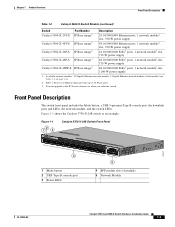
... 3750-X-48P switch as an example. Figure 1-2 Catalyst 3750-X-48P Switch Front Panel 23 1 MODE CONSOLE SYST EN XPS S-PWR STAT MAST SPEED STACK DUPLX PoE 12 34 56 78 9 10 11 12 13 14 15 16 17 18 19 20 21 22 23 24 25 26 27 28 29 30... 31 32 33 34 35 36 4 37 38 39 40 41 42 43 4C4ataly4s5t 46 3750-X 47 48 PoE+48 C3KX-NM-10G NMEOTWDUOLREK G1 G2/TE1 G3 G4/TE2 5 1 Mode button 2 USB Type-B console port 3 Status LEDs 4 10/100/1000 ports 5 Network Module...
... 3750-X-48P switch as an example. Figure 1-2 Catalyst 3750-X-48P Switch Front Panel 23 1 MODE CONSOLE SYST EN XPS S-PWR STAT MAST SPEED STACK DUPLX PoE 12 34 56 78 9 10 11 12 13 14 15 16 17 18 19 20 21 22 23 24 25 26 27 28 29 30... 31 32 33 34 35 36 4 37 38 39 40 41 42 43 4C4ataly4s5t 46 3750-X 47 48 PoE+48 C3KX-NM-10G NMEOTWDUOLREK G1 G2/TE1 G3 G4/TE2 5 1 Mode button 2 USB Type-B console port 3 Status LEDs 4 10/100/1000 ports 5 Network Module...

Hardware Installation Guide
Page 15
... switch internal power supply module(s) cannot support the total load, StackPower configurations allow the switch to 30 W) • Support for Cisco enhanced PoE • Support for prestandard Cisco powered devices • Configuration for Cisco intelligent power management, including enhanced power negotiation, power reservation, and per-port power policing Depending on page 2-27, and Appendix...
... switch internal power supply module(s) cannot support the total load, StackPower configurations allow the switch to 30 W) • Support for Cisco enhanced PoE • Support for prestandard Cisco powered devices • Configuration for Cisco intelligent power management, including enhanced power negotiation, power reservation, and per-port power policing Depending on page 2-27, and Appendix...

Hardware Installation Guide
Page 20
... Guide OL-19593-02 Front Panel Description Figure 1-3 Switch Front Panel LEDs MODE CONSOLE 123 45 SYST EN XPS S-PWR STAT MAST SPEED STACK DUPLX PoE Chapter 1 Product Overview System LED 251962 12 34 56 78 9 10 11 12 6 7 8 9 10 1 System LED 2 XPS1 LED 3 Status... . Switch is not functioning properly. Only Catalyst 3750-X switches. 3. There is a fault with PoE+ ports. 6 USB console port LED 7 S-PWR (StackPower) LED2 8 Master LED2 9 Stack LED2 10 PoE+ LED3 Table 1-6 System LED Color Off Green Blinking Green Blinking Amber Amber System Status System is operating...
... Guide OL-19593-02 Front Panel Description Figure 1-3 Switch Front Panel LEDs MODE CONSOLE 123 45 SYST EN XPS S-PWR STAT MAST SPEED STACK DUPLX PoE Chapter 1 Product Overview System LED 251962 12 34 56 78 9 10 11 12 6 7 8 9 10 1 System LED 2 XPS1 LED 3 Status... . Switch is not functioning properly. Only Catalyst 3750-X switches. 3. There is a fault with PoE+ ports. 6 USB console port LED 7 S-PWR (StackPower) LED2 8 Master LED2 9 Stack LED2 10 PoE+ LED3 Table 1-6 System LED Color Off Green Blinking Green Blinking Amber Amber System Status System is operating...
Hardware Installation Guide
Page 21
... power The PoE+ port status. 1. The XPS is providing power to another device (redundancy has been allocated to show the SPEED LED. For information about the XPS 2200, see the Cisco eXpandable Power System 2200 Hardware Installation Guide on page 1-14. OL-19593-02 Catalyst 3750-X ... or individually, display information about the switch and about the standby mode and fault conditions. See the "Stack LED (Catalyst 3750-X)" section on Cisco.com. SPEED Port speed The port operating speed: 10, 100, or 1000 Mb/s. This is connected and ready to this device). Table 1-8...
... power The PoE+ port status. 1. The XPS is providing power to another device (redundancy has been allocated to show the SPEED LED. For information about the XPS 2200, see the Cisco eXpandable Power System 2200 Hardware Installation Guide on page 1-14. OL-19593-02 Catalyst 3750-X ... or individually, display information about the switch and about the standby mode and fault conditions. See the "Stack LED (Catalyst 3750-X)" section on Cisco.com. SPEED Port speed The port operating speed: 10, 100, or 1000 Mb/s. This is connected and ready to this device). Table 1-8...

Hardware Installation Guide
Page 23
... port LED is off . Amber PoE+ for the port has been disabled. Table 1-10 USB Console Port LED Color Off Green Description USB console is enabled. USB console is disabled. Use only standard-compliant cabling to connect Cisco prestandard IP Phones and wireless access ...points or IEEE 802.3af-compliant devices to a PoE+ port. Only switches with PoE or PoE+ ports. OL-19593-02 Catalyst 3750-X and 3560-X Switch Hardware Installation Guide...
... port LED is off . Amber PoE+ for the port has been disabled. Table 1-10 USB Console Port LED Color Off Green Description USB console is enabled. USB console is disabled. Use only standard-compliant cabling to connect Cisco prestandard IP Phones and wireless access ...points or IEEE 802.3af-compliant devices to a PoE+ port. Only switches with PoE or PoE+ ports. OL-19593-02 Catalyst 3750-X and 3560-X Switch Hardware Installation Guide...

Hardware Installation Guide
Page 25
... mode is not selected on a switch with PoE+ ports, the PoE+ LED still shows detected PoE+ problems. Table 1-13 PoE+ Mode LED Color Off Green Blinking amber PoE+ Status PoE+ mode is not selected. PoE+ mode is not selected. PoE+ mode is selected, and the port LEDs show that switch 3 is a stack member. At least one of the... 34 56 78 9 10 11 12 1 MODE 2 34 5 CONSOLE SYST EN 6 78 XPS S-PWR STAT MAST 9 10 11 12 SPEED STACK DUPLX PoE 12 34 56 78 9 10 11 12 12 34 56 78 9 10 11 12 12 34 56 78 9 10 11 12 12 34 56 78 ...
... mode is not selected on a switch with PoE+ ports, the PoE+ LED still shows detected PoE+ problems. Table 1-13 PoE+ Mode LED Color Off Green Blinking amber PoE+ Status PoE+ mode is not selected. PoE+ mode is not selected. PoE+ mode is selected, and the port LEDs show that switch 3 is a stack member. At least one of the... 34 56 78 9 10 11 12 1 MODE 2 34 5 CONSOLE SYST EN 6 78 XPS S-PWR STAT MAST 9 10 11 12 SPEED STACK DUPLX PoE 12 34 56 78 9 10 11 12 12 34 56 78 9 10 11 12 12 34 56 78 9 10 11 12 12 34 56 78 ...

Hardware Installation Guide
Page 26
... Network Module LEDs Figure 1-5 Network Module LEDs (10-Gigabit Network Module Shown) 253212 37 38 39 40 41 42 43 4C4ataly4s5t 46 3750-X 47 48 PoE+48 C3KX-NM-10G NMEOTWDUOLREK G1 G2/TE1 G3 G4/TE2 1234 1 G1 LED 2 G2/TE1 LED 3 G3 LED 4 G4/TE2 LED Table 1-14 ... exceeded a limit set in the switch software. You must remove from the network any cable or device that causes a link fault. Link is connected to Cisco SFP and SFP+ ports. Amber Caution Link faults are caused when noncompliant cabling is on a link, no activity. Use only standard-compliant cabling to connect...
... Network Module LEDs Figure 1-5 Network Module LEDs (10-Gigabit Network Module Shown) 253212 37 38 39 40 41 42 43 4C4ataly4s5t 46 3750-X 47 48 PoE+48 C3KX-NM-10G NMEOTWDUOLREK G1 G2/TE1 G3 G4/TE2 1234 1 G1 LED 2 G2/TE1 LED 3 G3 LED 4 G4/TE2 LED Table 1-14 ... exceeded a limit set in the switch software. You must remove from the network any cable or device that causes a link fault. Link is connected to Cisco SFP and SFP+ ports. Amber Caution Link faults are caused when noncompliant cabling is on a link, no activity. Use only standard-compliant cabling to connect...

Hardware Installation Guide
Page 27
...-X switch rear panel, which has one connector for either a StackPower or an XPS connection, and one connector for StackPower. Figure 1-7 shows the Catalyst 3750-X-48 PoE+ switch, which has one connector only for XPS and no StackPower connector. Rear Panel Description The switch rear panel has a ground connector, an RJ-45...
...-X switch rear panel, which has one connector for either a StackPower or an XPS connection, and one connector for StackPower. Figure 1-7 shows the Catalyst 3750-X-48 PoE+ switch, which has one connector only for XPS and no StackPower connector. Rear Panel Description The switch rear panel has a ground connector, an RJ-45...

Hardware Installation Guide
Page 30
...software polls the device. Table 1-16 shows the power supply modules available for PoE and PoE+ PoE Option 24-Port Switch PoE (up to 15.4 W per port) (1) 715-W power supply (2) 440-W DC power supplies PoE+ (up to 8.7 W of PoE to power other devices. and 24-Port Switch SFP Switch Spare Spare C3KX-... removed or fails. Table 1-17 Switch Power Supply Requirements for Catalyst 3750-X and 3560-X switches and power supply configurations based on a 48-port PoE+ switch, you must use the CAB-3KX-250VAC-JP power cord with one 715-W power supply provides up to 30 W per port) (1) ...
...software polls the device. Table 1-16 shows the power supply modules available for PoE and PoE+ PoE Option 24-Port Switch PoE (up to 15.4 W per port) (1) 715-W power supply (2) 440-W DC power supplies PoE+ (up to 8.7 W of PoE to power other devices. and 24-Port Switch SFP Switch Spare Spare C3KX-... removed or fails. Table 1-17 Switch Power Supply Requirements for Catalyst 3750-X and 3560-X switches and power supply configurations based on a 48-port PoE+ switch, you must use the CAB-3KX-250VAC-JP power cord with one 715-W power supply provides up to 30 W per port) (1) ...
Hardware Installation Guide
Page 31
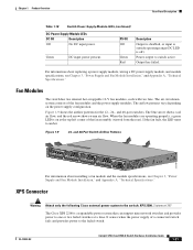
... 12 12 34 56 78 9 10 11 12 12 34 56 78 9 10 11 12 12 34 56 78 Catalys9 t 10 3750-X 11 12 PoE+48 C3KX-NM-10G NMEOTWDUOLREK G1 G2/TE1 G3 G4/TE2 For information about replacing a power supply module, wiring a DC power supply module, and module...Installation," and Appendix A, "Technical Specifications." Figure 1-9 shows the airflow patterns for the 12-, 24-, and 48-port switches. XPS Connector Warning Attach only the following Cisco external power system to amber. Power output to one or two failed switches at the top left corner of the fan assembly (viewed from the...
... 12 12 34 56 78 9 10 11 12 12 34 56 78 9 10 11 12 12 34 56 78 Catalys9 t 10 3750-X 11 12 PoE+48 C3KX-NM-10G NMEOTWDUOLREK G1 G2/TE1 G3 G4/TE2 For information about replacing a power supply module, wiring a DC power supply module, and module...Installation," and Appendix A, "Technical Specifications." Figure 1-9 shows the airflow patterns for the 12-, 24-, and 48-port switches. XPS Connector Warning Attach only the following Cisco external power system to amber. Power output to one or two failed switches at the top left corner of the fan assembly (viewed from the...

Hardware Installation Guide
Page 37
Caution To comply with the Telcordia GR-1089 NEBS standard, PoE or non-PoE 10/100/1000 Ethernet port cables that exit from the AC power outlet to all national laws and regulations. Access to the nearest rack metal. ...
Caution To comply with the Telcordia GR-1089 NEBS standard, PoE or non-PoE 10/100/1000 Ethernet port cables that exit from the AC power outlet to all national laws and regulations. Access to the nearest rack metal. ...

Hardware Installation Guide
Page 48
..., and the bottom switch is faulty. Installing the Switch Chapter 2 Switch Installation StackPower Partitioning Examples Figure 2-13 and Figure 2-14 show the Catalyst 3750-X-48 PoE switch as an example. In Figure 2-13, the StackPower cable 2 is now a separate stack. Therefore, this section show StackPower stacks of a StackPower Stack with a Failover...
..., and the bottom switch is faulty. Installing the Switch Chapter 2 Switch Installation StackPower Partitioning Examples Figure 2-13 and Figure 2-14 show the Catalyst 3750-X-48 PoE switch as an example. In Figure 2-13, the StackPower cable 2 is now a separate stack. Therefore, this section show StackPower stacks of a StackPower Stack with a Failover...

Hardware Installation Guide
Page 52
...Chapter 2 Switch Installation Mounting the Switch in a Rack 3 MODE CONSOLE SYST EN XPS S-PWR STAT MAST SPEED STACK DUPLX PoE 12 34 56 78 9 10 11 12 13 14 15 16 17 18 19 20 21 22 23 24 25 26 ... NMEOTWDUOLREK G1 G2/TE1 G3 G4/TE2 4 5 MODE CONSOLE SYST EN XPS S-PWR STAT MAST SPEED STACK DUPLX PoE 12 34 56 78 9 10 11 12 13 14 15 16 17 18 19 20 21 22 23 24 25... 28 29 30 31 32 33 34 35 36 37 38 39 40 41 42 43 4C4ataly4s5t 46 3750-X 47 48 PoE+48 C3KX-NM-10G NMEOTWDUOLREK G1 G2/TE1 G3 G4/TE2 4 6 CONSOLE STACK 1 AUX RESET STACK 2 S-PWR ...
...Chapter 2 Switch Installation Mounting the Switch in a Rack 3 MODE CONSOLE SYST EN XPS S-PWR STAT MAST SPEED STACK DUPLX PoE 12 34 56 78 9 10 11 12 13 14 15 16 17 18 19 20 21 22 23 24 25 26 ... NMEOTWDUOLREK G1 G2/TE1 G3 G4/TE2 4 5 MODE CONSOLE SYST EN XPS S-PWR STAT MAST SPEED STACK DUPLX PoE 12 34 56 78 9 10 11 12 13 14 15 16 17 18 19 20 21 22 23 24 25... 28 29 30 31 32 33 34 35 36 37 38 39 40 41 42 43 4C4ataly4s5t 46 3750-X 47 48 PoE+48 C3KX-NM-10G NMEOTWDUOLREK G1 G2/TE1 G3 G4/TE2 4 6 CONSOLE STACK 1 AUX RESET STACK 2 S-PWR ...

Hardware Installation Guide
Page 59
Figure 2-23 Installing an SFP Module in the Network Module 253158 37 38 39 40 41 42 43 8 Catalys9 t 10 3750-X 11 12 PoE+48 C3KX-NM-10G NMEOTWDUOLREK G1 G2/TE1 G3 G4/TE2 Step 5 Step 6 Step 7 If the module has a bale-clasp latch, close it to the ...
Figure 2-23 Installing an SFP Module in the Network Module 253158 37 38 39 40 41 42 43 8 Catalys9 t 10 3750-X 11 12 PoE+48 C3KX-NM-10G NMEOTWDUOLREK G1 G2/TE1 G3 G4/TE2 Step 5 Step 6 Step 7 If the module has a bale-clasp latch, close it to the ...

Hardware Installation Guide
Page 60
... has a bale-clasp latch, pull the bale out and down to the Ethernet Ports • 10/100/1000 Ethernet Port Connections, page 2-27 • PoE+ Port Connections, page 2-27 Caution Category 5e and Category 6 cables can store high levels of the SFP module to keep the optical interfaces clean. If... Figure 2-24 Network Module with SFP Modules Installed 12 C3KX-NM-10G NMEOTWDUOLREK 37 38 39 40 41 42 43 4C4ataly4s5t 46 3750-X 47 48 PoE+48 G1 G2/TE1 G3 34 G4/TE2 1 Network module 2 SFP modules 3 Send (TX) optical bore 4 Receive (RX) optical bore 253157 Chapter 2 Switch Installation...
... has a bale-clasp latch, pull the bale out and down to the Ethernet Ports • 10/100/1000 Ethernet Port Connections, page 2-27 • PoE+ Port Connections, page 2-27 Caution Category 5e and Category 6 cables can store high levels of the SFP module to keep the optical interfaces clean. If... Figure 2-24 Network Module with SFP Modules Installed 12 C3KX-NM-10G NMEOTWDUOLREK 37 38 39 40 41 42 43 4C4ataly4s5t 46 3750-X 47 48 PoE+48 G1 G2/TE1 G3 34 G4/TE2 1 Network module 2 SFP modules 3 Send (TX) optical bore 4 Receive (RX) optical bore 253157 Chapter 2 Switch Installation...
