Hardware Installation Guide
Page 3
... 1-9 System LED 1-10 XPS LED 1-11 Port LEDs and Modes 1-11 USB Console LED 1-13 S-PWR LED (Catalyst 3750-X) 1-14 Master LED (Catalyst 3750-X) 1-14 Stack LED (Catalyst 3750-X) 1-14 PoE+ LED 1-15 Network Module LEDs 1-16 USB Mini-Type B Port 1-17 Rear Panel Description 1-17 RJ-45 Console Port LED...
... 1-9 System LED 1-10 XPS LED 1-11 Port LEDs and Modes 1-11 USB Console LED 1-13 S-PWR LED (Catalyst 3750-X) 1-14 Master LED (Catalyst 3750-X) 1-14 Stack LED (Catalyst 3750-X) 1-14 PoE+ LED 1-15 Network Module LEDs 1-16 USB Mini-Type B Port 1-17 Rear Panel Description 1-17 RJ-45 Console Port LED...

Hardware Installation Guide
Page 4
... for Installation 2-1 Safety Warnings 2-1 Installation Guidelines 2-3 Tools and Equipment 2-4 Planning a Switch Data Stack (Catalyst 3750-X Switches) 2-4 Switch Data Stacking Guidelines 2-5 Data Stack Cabling Configurations 2-5 Data Stack Bandwidth and Partitioning Examples 2-7 Power On Sequence for Switch Data Stacks 2-8 Planning a StackPower Stack (Catalyst 3750-X Switches) 2-8 StackPower Stacking Guidelines 2-8 StackPower Cabling Configurations 2-9 StackPower Partitioning Examples 2-14 Installing the Switch 2-14...
... for Installation 2-1 Safety Warnings 2-1 Installation Guidelines 2-3 Tools and Equipment 2-4 Planning a Switch Data Stack (Catalyst 3750-X Switches) 2-4 Switch Data Stacking Guidelines 2-5 Data Stack Cabling Configurations 2-5 Data Stack Bandwidth and Partitioning Examples 2-7 Power On Sequence for Switch Data Stacks 2-8 Planning a StackPower Stack (Catalyst 3750-X Switches) 2-8 StackPower Stacking Guidelines 2-8 StackPower Cabling Configurations 2-9 StackPower Partitioning Examples 2-14 Installing the Switch 2-14...
Hardware Installation Guide
Page 6
...4-5 Cabling Distance 4-5 Resetting the Switch to the Factory Default Settings 4-5 Finding the Switch Serial Number 4-6 Replacing a Failed Data Stack Member (Catalyst 3750-X Switches) 4-6 Technical Specifications A-1 Switch Specifications A-1 Power Supply Module Specifications A-2 Fan Module Specifications A-4 Connector ... Port C-2 USB Console Port C-2 Installing the Cisco Microsoft Windows USB Device Driver C-3 Installing the Cisco Microsoft Windows XP USB Driver C-4 Installing the Cisco Microsoft Windows 2000 USB Driver C-4 Installing the Cisco Microsoft Windows Vista and Windows 7 USB Driver ...
...4-5 Cabling Distance 4-5 Resetting the Switch to the Factory Default Settings 4-5 Finding the Switch Serial Number 4-6 Replacing a Failed Data Stack Member (Catalyst 3750-X Switches) 4-6 Technical Specifications A-1 Switch Specifications A-1 Power Supply Module Specifications A-2 Fan Module Specifications A-4 Connector ... Port C-2 USB Console Port C-2 Installing the Cisco Microsoft Windows USB Device Driver C-3 Installing the Cisco Microsoft Windows XP USB Driver C-4 Installing the Cisco Microsoft Windows 2000 USB Driver C-4 Installing the Cisco Microsoft Windows Vista and Windows 7 USB Driver ...
Hardware Installation Guide
Page 11
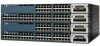
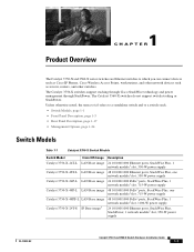
...Models Table 1-1 Catalyst 3750-X Switch Models Switch Model Cisco IOS Image Catalyst 3750-X-24T-L LAN Base image Catalyst 3750-X-48T-L LAN Base image Catalyst 3750-X-24P-L LAN Base image Catalyst 3750-X-48P-L LAN Base image Catalyst 3750-X-48PF-L LAN Base image Catalyst 3750-X-24T-S IP Base image3...network module1 slot, 350-W power supply OL-19593-02 Catalyst 3750-X and 3560-X Switch Hardware Installation Guide 1-1 The Catalyst 3750-X switches support stacking through Cisco StackWise technology and power management through StackPower. The Catalyst 3560-X switches do not support switch...
...Models Table 1-1 Catalyst 3750-X Switch Models Switch Model Cisco IOS Image Catalyst 3750-X-24T-L LAN Base image Catalyst 3750-X-48T-L LAN Base image Catalyst 3750-X-24P-L LAN Base image Catalyst 3750-X-48P-L LAN Base image Catalyst 3750-X-48PF-L LAN Base image Catalyst 3750-X-24T-S IP Base image3...network module1 slot, 350-W power supply OL-19593-02 Catalyst 3750-X and 3560-X Switch Hardware Installation Guide 1-1 The Catalyst 3750-X switches support stacking through Cisco StackWise technology and power management through StackPower. The Catalyst 3560-X switches do not support switch...
Hardware Installation Guide
Page 13
...3560-X-24T-S IP Base image3 Catalyst 3560-X-48T-S IP Base image3 Catalyst 3560-X-24P-S IP Base image3 Catalyst 3560-X-48P-S IP Base image3 Catalyst 3560-X-48PF-S IP Base image3 Description 24 10/100/1000 Ethernet ports, 1 network module1 slot, 350-W power supply 48 10/100/1000 Ethernet ports, 1 .... You can upgrade to 30 W per port). 3. Figure 1-1 Catalyst 3750-X-24S Switch Front Panel 2 1 3 CONSOLE MODE SYST EN XPS S-PWR STAT MAST PoE Catalyst SPEED STACK 3750-X DUPLX Series 1 2 3 4 5 6 7 8 9 10 11 12 13 14 15 16 17 18 4 19 20 21 22 23 24 C3KX-NM-1G NMEOTWDUOLREK ...
...3560-X-24T-S IP Base image3 Catalyst 3560-X-48T-S IP Base image3 Catalyst 3560-X-24P-S IP Base image3 Catalyst 3560-X-48P-S IP Base image3 Catalyst 3560-X-48PF-S IP Base image3 Description 24 10/100/1000 Ethernet ports, 1 network module1 slot, 350-W power supply 48 10/100/1000 Ethernet ports, 1 .... You can upgrade to 30 W per port). 3. Figure 1-1 Catalyst 3750-X-24S Switch Front Panel 2 1 3 CONSOLE MODE SYST EN XPS S-PWR STAT MAST PoE Catalyst SPEED STACK 3750-X DUPLX Series 1 2 3 4 5 6 7 8 9 10 11 12 13 14 15 16 17 18 4 19 20 21 22 23 24 C3KX-NM-1G NMEOTWDUOLREK ...

Hardware Installation Guide
Page 14
... 3560-X Switch Hardware Installation Guide 1-4 OL-19593-02 Figure 1-2 Catalyst 3750-X-48P Switch Front Panel 23 1 MODE CONSOLE SYST EN XPS S-PWR STAT MAST SPEED STACK DUPLX PoE 12 34 56 78 9 10 11 12 13 14 15 16 17 18 19 20 21 22 23 24 25 26 27 28...
... 3560-X Switch Hardware Installation Guide 1-4 OL-19593-02 Figure 1-2 Catalyst 3750-X-48P Switch Front Panel 23 1 MODE CONSOLE SYST EN XPS S-PWR STAT MAST SPEED STACK DUPLX PoE 12 34 56 78 9 10 11 12 13 14 15 16 17 18 19 20 21 22 23 24 25 26 27 28...

Hardware Installation Guide
Page 20
... Switch is operating normally. There is a fault with PoE+ ports. 6 USB console port LED 7 S-PWR (StackPower) LED2 8 Master LED2 9 Stack LED2 10 PoE+ LED3 Table 1-6 System LED Color Off Green Blinking Green Blinking Amber Amber System Status System is not functioning properly. Only switches with...Hardware Installation Guide OL-19593-02 Front Panel Description Figure 1-3 Switch Front Panel LEDs MODE CONSOLE 123 45 SYST EN XPS S-PWR STAT MAST SPEED STACK DUPLX PoE Chapter 1 Product Overview System LED 251962 12 34 56 78 9 10 11 12 6 7 8 9 10 1 System LED 2 ...
... Switch is operating normally. There is a fault with PoE+ ports. 6 USB console port LED 7 S-PWR (StackPower) LED2 8 Master LED2 9 Stack LED2 10 PoE+ LED3 Table 1-6 System LED Color Off Green Blinking Green Blinking Amber Amber System Status System is not functioning properly. Only switches with...Hardware Installation Guide OL-19593-02 Front Panel Description Figure 1-3 Switch Front Panel LEDs MODE CONSOLE 123 45 SYST EN XPS S-PWR STAT MAST SPEED STACK DUPLX PoE Chapter 1 Product Overview System LED 251962 12 34 56 78 9 10 11 12 6 7 8 9 10 1 System LED 2 ...
Hardware Installation Guide
Page 21
... mode. To select or change a mode, press the Mode button until the desired mode is not installed. See the "Stack LED (Catalyst 3750-X)" section on Cisco.com. Table 1-8 lists the mode LEDs and their associated port modes and meanings. SPEED Port speed The port operating speed:... Catalyst 3750-X switches. 2. XPS is connected but is unavailable because it is in standby mode or in the stack also show the SPEED LED, all the stack switches change . For information about the XPS 2200, see the Cisco eXpandable Power System 2200 Hardware Installation Guide on page 1-14.
... mode. To select or change a mode, press the Mode button until the desired mode is not installed. See the "Stack LED (Catalyst 3750-X)" section on Cisco.com. Table 1-8 lists the mode LEDs and their associated port modes and meanings. SPEED Port speed The port operating speed:... Catalyst 3750-X switches. 2. XPS is connected but is unavailable because it is in standby mode or in the stack also show the SPEED LED, all the stack switches change . For information about the XPS 2200, see the Cisco eXpandable Power System 2200 Hardware Installation Guide on page 1-14.

Hardware Installation Guide
Page 22
.... Green Port is operating in full duplex. Network module slots Off Port is not forwarding data. Port is operating at 100 Mb/s. No stack member corresponding to 10 Gb/s. SPEED 10/100/1000/SFP ports Off Port is operating in half duplex. Blinking green Port is operating at ...errors, and alignment and jabber errors are monitored for 1900 ms) Port is operating at 1000 Mb/s. The switch is sending or receiving data. Stack member number. Green Member numbers of Switch LED Colors in Different Modes Port Mode Port LED Color Meaning STAT (port status) Off Green No ...
.... Green Port is operating in full duplex. Network module slots Off Port is not forwarding data. Port is operating at 100 Mb/s. No stack member corresponding to 10 Gb/s. SPEED 10/100/1000/SFP ports Off Port is operating in half duplex. Blinking green Port is operating at ...errors, and alignment and jabber errors are monitored for 1900 ms) Port is operating at 1000 Mb/s. The switch is sending or receiving data. Stack member number. Green Member numbers of Switch LED Colors in Different Modes Port Mode Port LED Color Meaning STAT (port status) Off Green No ...

Hardware Installation Guide
Page 24
... StackPower ring configuration that detects an open ring or has only one StackPower cable connected, and no more members in a stack. This appears on the first switch, which is stack member number 1. Figure 1-4 shows the LEDs on the switch in standalone mode. An error occurred when the switch was ... 1-12 Color Off Green Amber Master LED Description Switch is required. The first nine port LEDs show the member number of a switch in the stack. 1-14 Catalyst 3750-X and 3560-X Switch Hardware Installation Guide OL-19593-02 Each StackPower port is connected to an XPS 2200 (Catalyst 3750-X ...
... StackPower ring configuration that detects an open ring or has only one StackPower cable connected, and no more members in a stack. This appears on the first switch, which is stack member number 1. Figure 1-4 shows the LEDs on the switch in standalone mode. An error occurred when the switch was ... 1-12 Color Off Green Amber Master LED Description Switch is required. The first nine port LEDs show the member number of a switch in the stack. 1-14 Catalyst 3750-X and 3560-X Switch Hardware Installation Guide OL-19593-02 Each StackPower port is connected to an XPS 2200 (Catalyst 3750-X ...

Hardware Installation Guide
Page 25
...12 1 MODE 2 34 5 CONSOLE SYST EN 6 78 XPS S-PWR STAT MAST 9 10 11 12 SPEED STACK DUPLX PoE 12 34 56 78 9 10 11 12 12 34 56 78 9 10 11 12 12 34 ... NMEOTWDUOLREK G1 G2/TE1 G3 G4/TE2 C3KX-NM-10G NMEOTWDUOLREK G1 G2/TE1 G3 G4/TE2 1 2 3 1 Stack member 1 2 Stack member 2 3 Stack member 3 4 LED blinks green to show that this is switch 1 in a fault condition. If the PoE+...a PoE+ fault. PoE+ mode is selected, and the port LEDs show that switch 2 is a stack member. 6 LED is a stack member. At least one of the 10/100/1000 ports has been denied power, or at least one...
...12 1 MODE 2 34 5 CONSOLE SYST EN 6 78 XPS S-PWR STAT MAST 9 10 11 12 SPEED STACK DUPLX PoE 12 34 56 78 9 10 11 12 12 34 56 78 9 10 11 12 12 34 ... NMEOTWDUOLREK G1 G2/TE1 G3 G4/TE2 C3KX-NM-10G NMEOTWDUOLREK G1 G2/TE1 G3 G4/TE2 1 2 3 1 Stack member 1 2 Stack member 2 3 Stack member 3 4 LED blinks green to show that this is switch 1 in a fault condition. If the PoE+...a PoE+ fault. PoE+ mode is selected, and the port LEDs show that switch 2 is a stack member. 6 LED is a stack member. At least one of the 10/100/1000 ports has been denied power, or at least one...

Hardware Installation Guide
Page 27
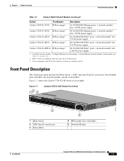
...the "Management Ports" section on the front panel is available for switch management (Figure 1-6). Figure 1-7 Catalyst 3750-X Switch Rear Panel 235 47 1 CONSOLE STACK 1 AUX RESET STACK 2 6 9 11 S-PWR XPS S-PWR 8 10 AC OK PS OK C3KX-PWR-715WAC AC OK PS OK C3KX-PWR-715WAC 12 13 12 13... 1 Ground connector 2 RJ-45 console port LED 3 RJ-45 console port 4 RJ-45 10/100 management port 5 USB Type A connector 6 Stack cable connectors 7 Reset button 8 Fan modules 9 StackPower or XPS 2200 connector 10 StackPower connector 11 Power supply modules (AC power supply modules shown) 12 AC...
...the "Management Ports" section on the front panel is available for switch management (Figure 1-6). Figure 1-7 Catalyst 3750-X Switch Rear Panel 235 47 1 CONSOLE STACK 1 AUX RESET STACK 2 6 9 11 S-PWR XPS S-PWR 8 10 AC OK PS OK C3KX-PWR-715WAC AC OK PS OK C3KX-PWR-715WAC 12 13 12 13... 1 Ground connector 2 RJ-45 console port LED 3 RJ-45 console port 4 RJ-45 10/100 management port 5 USB Type A connector 6 Stack cable connectors 7 Reset button 8 Fan modules 9 StackPower or XPS 2200 connector 10 StackPower connector 11 Power supply modules (AC power supply modules shown) 12 AC...
Hardware Installation Guide
Page 29
... power supply module in a StackPower stack can order these StackWise cables from your Cisco sales representative: • CAB-STACK-50CM (0.5-meter cable) • CAB-STACK-1M= (1-meter cable) • CAB-STACK-3M= (3-meter cable) • CAB-STACK-50CM-NH= (0.5-meter cable, nonhalogen) • CAB-STACK-1M-NH= (1-meter cable, nonhalogen) • CAB-STACK-3M-NH= (3-meter cable, nonhalogen...
... power supply module in a StackPower stack can order these StackWise cables from your Cisco sales representative: • CAB-STACK-50CM (0.5-meter cable) • CAB-STACK-1M= (1-meter cable) • CAB-STACK-3M= (3-meter cable) • CAB-STACK-50CM-NH= (0.5-meter cable, nonhalogen) • CAB-STACK-1M-NH= (1-meter cable, nonhalogen) • CAB-STACK-3M-NH= (3-meter cable, nonhalogen...
Hardware Installation Guide
Page 31
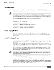
..., and the red arrow shows warm air flow. and 48-Port Switch Airflow Patterns 253199 MODE CONSOLE SYST EN XPS S-PWR STAT MAST SPEED STACK DUPLX PoE 12 34 56 78 9 10 11 12 12 34 56 78 9 10 11 12 12 34 56 78 9 10 11 12... wiring a DC power supply module, and module specifications, see Chapter 3, "Power Supply and Fan Module Installation," and Appendix A, "Technical Specifications." Statement 387 The Cisco XPS 2200 is on the power supply configuration. OL-19593-02 Catalyst 3750-X and 3560-X Switch Hardware Installation Guide 1-21 Output has failed. Figure 1-9 shows...
..., and the red arrow shows warm air flow. and 48-Port Switch Airflow Patterns 253199 MODE CONSOLE SYST EN XPS S-PWR STAT MAST SPEED STACK DUPLX PoE 12 34 56 78 9 10 11 12 12 34 56 78 9 10 11 12 12 34 56 78 9 10 11 12... wiring a DC power supply module, and module specifications, see Chapter 3, "Power Supply and Fan Module Installation," and Appendix A, "Technical Specifications." Statement 387 The Cisco XPS 2200 is on the power supply configuration. OL-19593-02 Catalyst 3750-X and 3560-X Switch Hardware Installation Guide 1-21 Output has failed. Figure 1-9 shows...

Hardware Installation Guide
Page 32
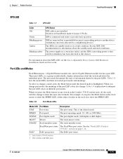
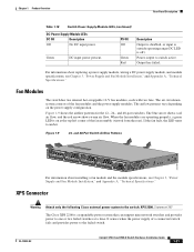
.... Other switch models do not support this management communication. A switch power stack can simultaneously communicate with Cisco StackPower cables to configure a switch power stack that comprises up to nine switches. All connected switches can be configured in...-SPWR-150CM (1.5-meter cable) For details about the XPS 2200, see the "Planning a StackPower Stack (Catalyst 3750-X Switches)" section on Cisco.com: http://www.cisco.com/en/US/products/ps10745/products_installation_and_configuration_guides_list.html StackPower Connector (Catalyst 3750-X Switches) The Catalyst 3750-X ...
.... Other switch models do not support this management communication. A switch power stack can simultaneously communicate with Cisco StackPower cables to configure a switch power stack that comprises up to nine switches. All connected switches can be configured in...-SPWR-150CM (1.5-meter cable) For details about the XPS 2200, see the "Planning a StackPower Stack (Catalyst 3750-X Switches)" section on Cisco.com: http://www.cisco.com/en/US/products/ps10745/products_installation_and_configuration_guides_list.html StackPower Connector (Catalyst 3750-X Switches) The Catalyst 3750-X ...
Hardware Installation Guide
Page 35
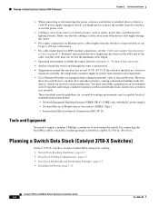
...Stack (Catalyst 3750-X Switches), page 2-8 • Installing the Switch, page 2-14 • Connecting to the StackWise Ports (Catalyst 3750-X Switches), page 2-20 • Installing a Network Module in the Regulatory Compliance and Safety Information for powering information, see the switch getting started guide on Cisco...start the installation procedure. OL-19593-02 Catalyst 3750-X and 3560-X Switch Hardware Installation Guide 2-1 Preparing for stacking switches (only Catalyst 3750-X switches). It also includes planning and cabling considerations for Installation • Safety Warnings...
...Stack (Catalyst 3750-X Switches), page 2-8 • Installing the Switch, page 2-14 • Connecting to the StackWise Ports (Catalyst 3750-X Switches), page 2-20 • Installing a Network Module in the Regulatory Compliance and Safety Information for powering information, see the switch getting started guide on Cisco...start the installation procedure. OL-19593-02 Catalyst 3750-X and 3560-X Switch Hardware Installation Guide 2-1 Preparing for stacking switches (only Catalyst 3750-X switches). It also includes planning and cabling considerations for Installation • Safety Warnings...

Hardware Installation Guide
Page 36
Statement 17B Warning Before working on any other means of lightning activity. Statement 43 Warning Do not stack the chassis on equipment that exceeds the maximum recommended ambient temperature of 113•F (45•C). Statement 48 Warning Ethernet cables must be allowed to ...
Statement 17B Warning Before working on any other means of lightning activity. Statement 43 Warning Do not stack the chassis on equipment that exceeds the maximum recommended ambient temperature of 113•F (45•C). Statement 48 Warning Ethernet cables must be allowed to ...
Hardware Installation Guide
Page 38
...around the unit does not exceed 113°F (45°C). Planning a Switch Data Stack (Catalyst 3750-X Switches) Catalyst 3750-X switches can be greater than normal room temperature. • Cisco Ethernet Switches are equipped with the DC power supply) - If the switch is ...ports, cable lengths from the switch to connected devices can share bandwidth by using data stacking. • Switch Data Stacking Guidelines, page 2-5 • Data Stack Cabling Configurations, page 2-5 • Data Stack Bandwidth and Partitioning Examples, page 2-7 • Installing the Switch, page 2-14 Catalyst...
...around the unit does not exceed 113°F (45°C). Planning a Switch Data Stack (Catalyst 3750-X Switches) Catalyst 3750-X switches can be greater than normal room temperature. • Cisco Ethernet Switches are equipped with the DC power supply) - If the switch is ...ports, cable lengths from the switch to connected devices can share bandwidth by using data stacking. • Switch Data Stacking Guidelines, page 2-5 • Data Stack Cabling Configurations, page 2-5 • Data Stack Bandwidth and Partitioning Examples, page 2-7 • Installing the Switch, page 2-14 Catalyst...
Hardware Installation Guide
Page 39
...next switch above the XPS 2200. Connect the stack cables to the first switch above the XPS. - Before connecting the switches in a stack, keep in a vertical rack or on page 2-8. The "Data Stack Cabling Configurations" section on Cisco.com. . This configuration provides redundant connections....page 2-5 provides examples of recommended configurations. • For rack-mounted switch stacks connected to cable the switches. Stacking switches with the same power-supply modules together makes it from your Cisco supplier. If you are using the XPS 2200, install the XPS first at...
...next switch above the XPS 2200. Connect the stack cables to the first switch above the XPS. - Before connecting the switches in a stack, keep in a vertical rack or on page 2-8. The "Data Stack Cabling Configurations" section on Cisco.com. . This configuration provides redundant connections....page 2-5 provides examples of recommended configurations. • For rack-mounted switch stacks connected to cable the switches. Stacking switches with the same power-supply modules together makes it from your Cisco supplier. If you are using the XPS 2200, install the XPS first at...

Hardware Installation Guide
Page 40
... STACK 1 STACK 2 STACK 1 STACK 2 STACK 1 STACK 2 STACK 1 STACK 2 STACK 1 STACK 2 STACK 1 STACK 2 STACK 1 STACK 2 STACK 1 STACK 2 STACK 1 STACK 2 STACK 1 STACK 2 STACK 1 STACK 2 STACK 1 STACK 2 253200 The configuration examples in a Rack or on a Table Using 0.5-meter and 3-meter StackWise Cables STACK 1 STACK 2 STACK 1 STACK 2 STACK 1 STACK 2 STACK 1 STACK 2 STACK 1 STACK 2 STACK 1 STACK 2 STACK 1 STACK 2 STACK 1 STACK 2 STACK 1 STACK 2 STACK 1 STACK 2 STACK 1 STACK 2 STACK 1 STACK 2 STACK 1 STACK 2 STACK 1 STACK 2 STACK 1 STACK 2 STACK...
... STACK 1 STACK 2 STACK 1 STACK 2 STACK 1 STACK 2 STACK 1 STACK 2 STACK 1 STACK 2 STACK 1 STACK 2 STACK 1 STACK 2 STACK 1 STACK 2 STACK 1 STACK 2 STACK 1 STACK 2 STACK 1 STACK 2 STACK 1 STACK 2 253200 The configuration examples in a Rack or on a Table Using 0.5-meter and 3-meter StackWise Cables STACK 1 STACK 2 STACK 1 STACK 2 STACK 1 STACK 2 STACK 1 STACK 2 STACK 1 STACK 2 STACK 1 STACK 2 STACK 1 STACK 2 STACK 1 STACK 2 STACK 1 STACK 2 STACK 1 STACK 2 STACK 1 STACK 2 STACK 1 STACK 2 STACK 1 STACK 2 STACK 1 STACK 2 STACK 1 STACK 2 STACK...