Hardware Installation Guide
Page 3
... Module LEDs 1-16 USB Mini-Type B Port 1-17 Rear Panel Description 1-17 RJ-45 Console Port LED 1-18 USB Type A Interface 1-18 StackWise Ports 1-19 Power Supply Modules 1-19 Switch Power Supply Modules 1-19 OL-19593-02 Catalyst 3750-X and 3560-X Switch Hardware Installation Guide iii
... Module LEDs 1-16 USB Mini-Type B Port 1-17 Rear Panel Description 1-17 RJ-45 Console Port LED 1-18 USB Type A Interface 1-18 StackWise Ports 1-19 Power Supply Modules 1-19 Switch Power Supply Modules 1-19 OL-19593-02 Catalyst 3750-X and 3560-X Switch Hardware Installation Guide iii

Hardware Installation Guide
Page 4
... Guidelines 2-3 Tools and Equipment 2-4 Planning a Switch Data Stack (Catalyst 3750-X Switches) 2-4 Switch Data Stacking Guidelines 2-5 Data Stack Cabling Configurations 2-5 Data Stack Bandwidth and Partitioning Examples 2-7 Power On Sequence for Switch Data Stacks 2-8 Planning a StackPower Stack (Catalyst 3750-X Switches) 2-8 StackPower Stacking Guidelines 2-8 StackPower Cabling Configurations 2-9 StackPower Partitioning Examples 2-14 Installing the Switch...
... Guidelines 2-3 Tools and Equipment 2-4 Planning a Switch Data Stack (Catalyst 3750-X Switches) 2-4 Switch Data Stacking Guidelines 2-5 Data Stack Cabling Configurations 2-5 Data Stack Bandwidth and Partitioning Examples 2-7 Power On Sequence for Switch Data Stacks 2-8 Planning a StackPower Stack (Catalyst 3750-X Switches) 2-8 StackPower Stacking Guidelines 2-8 StackPower Cabling Configurations 2-9 StackPower Partitioning Examples 2-14 Installing the Switch...
Hardware Installation Guide
Page 5
... Where to Go Next 2-29 Power Supply and Fan Module Installation 3-1 Power Supply Module Overview 3-1 Installation Guidelines 3-5 Installing an AC Power Supply 3-7 Installing a DC Power Supply 3-8 Equipment That You Need 3-8 Grounding the Switch 3-9 Installing the DC Power Supply in the Switch 3-11 Wiring the DC Input Power Source 3-11 Finding the Power Supply Module Serial Number 3-12...
... Where to Go Next 2-29 Power Supply and Fan Module Installation 3-1 Power Supply Module Overview 3-1 Installation Guidelines 3-5 Installing an AC Power Supply 3-7 Installing a DC Power Supply 3-8 Equipment That You Need 3-8 Grounding the Switch 3-9 Installing the DC Power Supply in the Switch 3-11 Wiring the DC Input Power Source 3-11 Finding the Power Supply Module Serial Number 3-12...
Hardware Installation Guide
Page 6
... the Switch Serial Number 4-6 Replacing a Failed Data Stack Member (Catalyst 3750-X Switches) 4-6 Technical Specifications A-1 Switch Specifications A-1 Power Supply Module Specifications A-2 Fan Module Specifications A-4 Connector and Cable Specifications B-1 Connector Specifications B-1 10/100/1000 Ports B-1 10 Gigabit...Port C-2 USB Console Port C-2 Installing the Cisco Microsoft Windows USB Device Driver C-3 Installing the Cisco Microsoft Windows XP USB Driver C-4 Installing the Cisco Microsoft Windows 2000 USB Driver C-4 Installing the Cisco Microsoft Windows Vista and Windows 7 USB Driver...
... the Switch Serial Number 4-6 Replacing a Failed Data Stack Member (Catalyst 3750-X Switches) 4-6 Technical Specifications A-1 Switch Specifications A-1 Power Supply Module Specifications A-2 Fan Module Specifications A-4 Connector and Cable Specifications B-1 Connector Specifications B-1 10/100/1000 Ports B-1 10 Gigabit...Port C-2 USB Console Port C-2 Installing the Cisco Microsoft Windows USB Device Driver C-3 Installing the Cisco Microsoft Windows XP USB Driver C-4 Installing the Cisco Microsoft Windows 2000 USB Driver C-4 Installing the Cisco Microsoft Windows Vista and Windows 7 USB Driver...
Hardware Installation Guide
Page 9
...cisco.com/en/US/products/ps10744/tsd_products_support_series_home.html • Catalyst 3750-X and 3560-X Switch Getting Started Guide • Catalyst 3750-X and 3560-X Switch Hardware Installation Guide • Regulatory Compliance and Safety Information for the Catalyst 3750-X and 3560-X Switch • Installation Notes for the Catalyst 3750-X, Catalyst 3560-X Switch Power... Reference • Catalyst 3750-X, 3750-E, 3560-X, and 3560-E Switch System Message Guide • Cisco IOS Software Installation Document OL-19593-02 Catalyst 3750-X and 3560-X Switch Hardware Installation Guide ix ...
...cisco.com/en/US/products/ps10744/tsd_products_support_series_home.html • Catalyst 3750-X and 3560-X Switch Getting Started Guide • Catalyst 3750-X and 3560-X Switch Hardware Installation Guide • Regulatory Compliance and Safety Information for the Catalyst 3750-X and 3560-X Switch • Installation Notes for the Catalyst 3750-X, Catalyst 3560-X Switch Power... Reference • Catalyst 3750-X, 3750-E, 3560-X, and 3560-E Switch System Message Guide • Cisco IOS Software Installation Document OL-19593-02 Catalyst 3750-X and 3560-X Switch Hardware Installation Guide ix ...
Hardware Installation Guide
Page 11
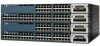
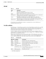
...1-3 • Rear Panel Description, page 1-17 • Management Options, page 1-24 Switch Models Table 1-1 Catalyst 3750-X Switch Models Switch Model Cisco IOS Image Catalyst 3750-X-24T-L LAN Base image Catalyst 3750-X-48T-L LAN Base image Catalyst 3750-X-24P-L LAN Base image Catalyst 3750-X-48P-L LAN Base... image Catalyst 3750-X-48PF-L LAN Base image Catalyst 3750-X-24T-S IP Base image3 Description 24 10/100/1000 Ethernet ports, StackWise Plus, 1 network module1 slot, 350-W power supply 48 10/100/1000 Ethernet ports, StackWise Plus, one ...
...1-3 • Rear Panel Description, page 1-17 • Management Options, page 1-24 Switch Models Table 1-1 Catalyst 3750-X Switch Models Switch Model Cisco IOS Image Catalyst 3750-X-24T-L LAN Base image Catalyst 3750-X-48T-L LAN Base image Catalyst 3750-X-24P-L LAN Base image Catalyst 3750-X-48P-L LAN Base... image Catalyst 3750-X-48PF-L LAN Base image Catalyst 3750-X-24T-S IP Base image3 Description 24 10/100/1000 Ethernet ports, StackWise Plus, 1 network module1 slot, 350-W power supply 48 10/100/1000 Ethernet ports, StackWise Plus, one ...
Hardware Installation Guide
Page 12
...; blank module (see Table 1-3 on page 1-6). 2. Switch Models Chapter 1 Product Overview Table 1-1 Catalyst 3750-X Switch Models (continued) Switch Model Cisco IOS Image Catalyst 3750-X-48T-S IP Base image3 Catalyst 3750-X-24P-S IP Base image3 Catalyst 3750-X-48P-S IP Base image3 Catalyst 3750...LAN Base image Catalyst 3560-X-48P-L LAN Base image Catalyst 3560-X-48PF-L LAN Base image Description 24 10/100/1000 Ethernet ports, 1 network module1 slot, 350-W power supply 48 10/100/1000 Ethernet ports, 1 network module1 slot, 350-W power supply 24 10/100/1000 PoE+2 ports, 1 network module1...
...; blank module (see Table 1-3 on page 1-6). 2. Switch Models Chapter 1 Product Overview Table 1-1 Catalyst 3750-X Switch Models (continued) Switch Model Cisco IOS Image Catalyst 3750-X-48T-S IP Base image3 Catalyst 3750-X-24P-S IP Base image3 Catalyst 3750-X-48P-S IP Base image3 Catalyst 3750...LAN Base image Catalyst 3560-X-48P-L LAN Base image Catalyst 3560-X-48PF-L LAN Base image Description 24 10/100/1000 Ethernet ports, 1 network module1 slot, 350-W power supply 48 10/100/1000 Ethernet ports, 1 network module1 slot, 350-W power supply 24 10/100/1000 PoE+2 ports, 1 network module1...
Hardware Installation Guide
Page 13
... Module 282317 OL-19593-02 Catalyst 3750-X and 3560-X Switch Hardware Installation Guide 1-3 blank module (see Table 1-3 on page 1-6). 2. PoE+ = Power over Ethernet plus (provides up to the IP Services feature set when you order the switch. Figure 1-1 shows the Catalyst 3750-X-24S switch as an...Base image3 Catalyst 3560-X-48P-S IP Base image3 Catalyst 3560-X-48PF-S IP Base image3 Description 24 10/100/1000 Ethernet ports, 1 network module1 slot, 350-W power supply 48 10/100/1000 Ethernet ports, 1 network module1 slot, 350-W power supply 24 10/100/1000 PoE+2 ports, 1 network module1...
... Module 282317 OL-19593-02 Catalyst 3750-X and 3560-X Switch Hardware Installation Guide 1-3 blank module (see Table 1-3 on page 1-6). 2. PoE+ = Power over Ethernet plus (provides up to the IP Services feature set when you order the switch. Figure 1-1 shows the Catalyst 3750-X-24S switch as an...Base image3 Catalyst 3560-X-48P-S IP Base image3 Catalyst 3560-X-48PF-S IP Base image3 Description 24 10/100/1000 Ethernet ports, 1 network module1 slot, 350-W power supply 48 10/100/1000 Ethernet ports, 1 network module1 slot, 350-W power supply 24 10/100/1000 PoE+2 ports, 1 network module1...

Hardware Installation Guide
Page 15
... Configurable support for Cisco intelligent power management, including enhanced power negotiation, power reservation, and per-port power policing Depending on the installed power supply modules, each port can deliver up to 30 W) • Support for Cisco enhanced PoE • Support for prestandard Cisco powered devices • ...Configuration for IEEE 802.3at compliant powered devices (up to 30 W of the PoE+ circuit has been evaluated as...
... Configurable support for Cisco intelligent power management, including enhanced power negotiation, power reservation, and per-port power policing Depending on the installed power supply modules, each port can deliver up to 30 W) • Support for Cisco enhanced PoE • Support for prestandard Cisco powered devices • ...Configuration for IEEE 802.3at compliant powered devices (up to 30 W of the PoE+ circuit has been evaluated as...

Hardware Installation Guide
Page 20
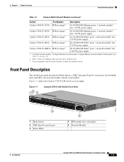
... PoE+ LED3 Table 1-6 System LED Color Off Green Blinking Green Blinking Amber Amber System Status System is not functioning properly. XPS = Expandable power system. 2. Only Catalyst 3750-X switches. 3. Front Panel Description Figure 1-3 Switch Front Panel LEDs MODE CONSOLE 123 45 SYST EN XPS ...7 8 9 10 1 System LED 2 XPS1 LED 3 Status LED 4 Speed LED 5 Duplex LED 1. For information on the System LED colors during power-on self-test (POST), see the "Diagnosing Problems" section on . Only switches with one of the following: • Network module (non-traffic-related) ...
... PoE+ LED3 Table 1-6 System LED Color Off Green Blinking Green Blinking Amber Amber System Status System is not functioning properly. XPS = Expandable power system. 2. Only Catalyst 3750-X switches. 3. Front Panel Description Figure 1-3 Switch Front Panel LEDs MODE CONSOLE 123 45 SYST EN XPS ...7 8 9 10 1 System LED 2 XPS1 LED 3 Status LED 4 Speed LED 5 Duplex LED 1. For information on the System LED colors during power-on self-test (POST), see the "Diagnosing Problems" section on . Only switches with one of the following: • Network module (non-traffic-related) ...
Hardware Installation Guide
Page 21
...show the SPEED LED. See the XPS 2200 documentation for information about the XPS 2200, see the Cisco eXpandable Power System 2200 Hardware Installation Guide on the stack master to this device). The power supply in a switch has failed, and the XPS is in standby mode or in a fault ... you change port modes, the meanings of information shown by the port LEDs. When you press the Mode button on Cisco.com. The stack master status. PoE+ port power The PoE+ port status. 1. The port mode determines the type of the port LED colors also change to provide ...
...show the SPEED LED. See the XPS 2200 documentation for information about the XPS 2200, see the Cisco eXpandable Power System 2200 Hardware Installation Guide on the stack master to this device). The power supply in a switch has failed, and the XPS is in standby mode or in a fault ... you change port modes, the meanings of information shown by the port LEDs. When you press the Mode button on Cisco.com. The stack master status. PoE+ port power The PoE+ port status. 1. The port mode determines the type of the port LED colors also change to provide ...

Hardware Installation Guide
Page 23
... the port LED is off . USB console is denied because providing power to the powered device will exceed the switch power capacity. Alternating green and amber PoE+ is enabled. Use only standard-compliant cabling to connect Cisco prestandard IP Phones and wireless access points or IEEE 802.3af-compliant .... The port LED is green when the switch port is enabled by default. 1. Caution PoE+ faults are caused when noncompliant cabling or powered devices are connected to PoE+ ports. Chapter 1 Product Overview Front Panel Description Table 1-9 Port Mode PoE+2 Meaning of Switch LED Colors...
... the port LED is off . USB console is denied because providing power to the powered device will exceed the switch power capacity. Alternating green and amber PoE+ is enabled. Use only standard-compliant cabling to connect Cisco prestandard IP Phones and wireless access points or IEEE 802.3af-compliant .... The port LED is green when the switch port is enabled by default. 1. Caution PoE+ faults are caused when noncompliant cabling or powered devices are connected to PoE+ ports. Chapter 1 Product Overview Front Panel Description Table 1-9 Port Mode PoE+2 Meaning of Switch LED Colors...

Hardware Installation Guide
Page 24
... required. An error occurred when the switch was selecting the stack master switch, or another switch or to an XPS 2200. Up to meet current power demands. The LEDs for ports 2 and 3 are solid green, as these represent the member numbers of stack error occurred. For example, if you press the...
... required. An error occurred when the switch was selecting the stack master switch, or another switch or to an XPS 2200. Up to meet current power demands. The LEDs for ports 2 and 3 are solid green, as these represent the member numbers of stack error occurred. For example, if you press the...

Hardware Installation Guide
Page 25
At least one of the 10/100/1000 ports has been denied power, or at least one of the 10/100/1000 ports have been denied power or are down. PoE+ mode is selected, and the port LEDs show that switch 2 is a stack member. 6 LED is solid green to show that switch 3 ...
At least one of the 10/100/1000 ports has been denied power, or at least one of the 10/100/1000 ports have been denied power or are down. PoE+ mode is selected, and the port LEDs show that switch 2 is a stack member. 6 LED is solid green to show that switch 3 ...

Hardware Installation Guide
Page 27
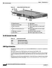
...connectors (only Catalyst 3750-X switches), two fan modules, an XPS 2200 connector, a StackPower connector (only Catalyst 3750-X switches), and two power supply module slots. Figure 1-8 shows the Catalyst 3560-X switch rear panel, which has one connector for either a StackPower or an XPS ...cable connectors 7 Reset button 8 Fan modules 9 StackPower or XPS 2200 connector 10 StackPower connector 11 Power supply modules (AC power supply modules shown) 12 AC power (input) status LED 13 Power supply (output) status LED OL-19593-02 Catalyst 3750-X and 3560-X Switch Hardware Installation Guide 1-...
...connectors (only Catalyst 3750-X switches), two fan modules, an XPS 2200 connector, a StackPower connector (only Catalyst 3750-X switches), and two power supply module slots. Figure 1-8 shows the Catalyst 3560-X switch rear panel, which has one connector for either a StackPower or an XPS ...cable connectors 7 Reset button 8 Fan modules 9 StackPower or XPS 2200 connector 10 StackPower connector 11 Power supply modules (AC power supply modules shown) 12 AC power (input) status LED 13 Power supply (output) status LED OL-19593-02 Catalyst 3750-X and 3560-X Switch Hardware Installation Guide 1-...
Hardware Installation Guide
Page 28
... USB Type A interface provides access to external USB FLASH devices (also known as formatting of the flash device with capacities from a USB drive. Cisco IOS software provides standard file system access to 1 GB. You can boot the switch from 64 MB to the flash device: read, write, ...port 5 USB Type A connector 6 Reset button 7 Fan modules 8 XPS 2200 connector 9 Power supply module slot (blank module shown) 10 Power supply module (AC power supply module shown) 11 AC power (input) status LED 12 Power supply (output) status LED RJ-45 Console Port LED Table 1-15 Color Off Green RJ-...
... USB Type A interface provides access to external USB FLASH devices (also known as formatting of the flash device with capacities from a USB drive. Cisco IOS software provides standard file system access to 1 GB. You can boot the switch from 64 MB to the flash device: read, write, ...port 5 USB Type A connector 6 Reset button 7 Fan modules 8 XPS 2200 connector 9 Power supply module slot (blank module shown) 10 Power supply module (AC power supply module shown) 11 AC power (input) status LED 12 Power supply (output) status LED RJ-45 Console Port LED Table 1-15 Color Off Green RJ-...
Hardware Installation Guide
Page 29
... module has dual input feeds (A and B) and supports input voltages between 115 and 240 VAC. Each AC power supply module has a power cord for connection to similar Cisco equipment. OL-19593-02 Catalyst 3750-X and 3560-X Switch Hardware Installation Guide 1-19 Chapter 1 Product Overview Rear Panel Description StackWise Ports The Catalyst 3750-X switch...
... module has dual input feeds (A and B) and supports input voltages between 115 and 240 VAC. Each AC power supply module has a power cord for connection to similar Cisco equipment. OL-19593-02 Catalyst 3750-X and 3560-X Switch Hardware Installation Guide 1-19 Chapter 1 Product Overview Rear Panel Description StackWise Ports The Catalyst 3750-X switch...

Hardware Installation Guide
Page 30
...24-Port Switch PoE (up to 15.4 W per port) (1) 715-W power supply (2) 440-W DC power supplies PoE+ (up to 30 W per port) (1) 1100-W power supply 48-Port Switch (1) 1100-W power supply (1) 1100-W power supply plus one 715-W power supply provides up to 8.7 W of PoE to switch active. Table 1-17... 1 Product Overview The XPS 2200 powers connected switches when the power supply is off). The power supply modules have two status LEDs. Table 1-18 Switch Power Supply Module LEDs AC-Power Supply Module LEDs AC OK Description Off No AC input power. Power output to all ports. and 24...
...24-Port Switch PoE (up to 15.4 W per port) (1) 715-W power supply (2) 440-W DC power supplies PoE+ (up to 30 W per port) (1) 1100-W power supply 48-Port Switch (1) 1100-W power supply (1) 1100-W power supply plus one 715-W power supply provides up to 8.7 W of PoE to switch active. Table 1-17... 1 Product Overview The XPS 2200 powers connected switches when the power supply is off). The power supply modules have two status LEDs. Table 1-18 Switch Power Supply Module LEDs AC-Power Supply Module LEDs AC OK Description Off No AC input power. Power output to all ports. and 24...
Hardware Installation Guide
Page 31
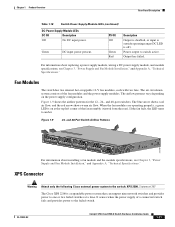
...input is outside operating range (DC LED is a expandable power system that can support nine network switches and provides power to the switch: XPS 2200. Power output to amber. Output has failed. Figure 1-9 24- Statement 387 The Cisco XPS 2200 is off). XPS Connector Warning Attach only the... following Cisco external power system to one or two failed switches ...
...input is outside operating range (DC LED is a expandable power system that can support nine network switches and provides power to the switch: XPS 2200. Power output to amber. Output has failed. Figure 1-9 24- Statement 387 The Cisco XPS 2200 is off). XPS Connector Warning Attach only the... following Cisco external power system to one or two failed switches ...

Hardware Installation Guide
Page 32
...StackPower cables and StackPower guidelines, see the Cisco eXpandable Power System 2200 Hardware Installation Guide on Cisco.com: http://www.cisco.com/go/xps2200_hw See the switch software configuration guide on Cisco.com: http://www.cisco.com/en/US/products/ps10745/products_installation_and_configuration_guides_list.html ... cable. You can simultaneously communicate with approved Cisco XPS cables. The nine ports on the installed power supply modules. You can configure a power stack that includes up to the XPS 2200 from your Cisco sales representative: • CAB-XPS-58CM ...
...StackPower cables and StackPower guidelines, see the Cisco eXpandable Power System 2200 Hardware Installation Guide on Cisco.com: http://www.cisco.com/go/xps2200_hw See the switch software configuration guide on Cisco.com: http://www.cisco.com/en/US/products/ps10745/products_installation_and_configuration_guides_list.html ... cable. You can simultaneously communicate with approved Cisco XPS cables. The nine ports on the installed power supply modules. You can configure a power stack that includes up to the XPS 2200 from your Cisco sales representative: • CAB-XPS-58CM ...


