Hardware Installation Guide
Page 3
...vii Obtaining Documentation and Submitting a Service Request viii Product Overview 1-1 Switch Models 1-1 Front Panel Description 1-3 SFP Module Slots 1-4 10/100/1000 Ethernet Ports 1-4 PoE+ Ports 1-5 Network Modules 1-5 SFP and SFP+ Modules 1-7 LEDs 1-9 System LED 1-10 XPS LED 1-11 Port LEDs and Modes 1-11 USB Console LED 1-13... S-PWR LED (Catalyst 3750-X) 1-14 Master LED (Catalyst 3750-X) 1-14 Stack LED (Catalyst 3750-X) 1-14 PoE+ LED 1-15 Network Module LEDs 1-16 USB Mini-Type B Port 1-17 Rear Panel Description 1-17 RJ-45 Console Port LED 1-18 USB Type A Interface 1-18 StackWise Ports...
...vii Obtaining Documentation and Submitting a Service Request viii Product Overview 1-1 Switch Models 1-1 Front Panel Description 1-3 SFP Module Slots 1-4 10/100/1000 Ethernet Ports 1-4 PoE+ Ports 1-5 Network Modules 1-5 SFP and SFP+ Modules 1-7 LEDs 1-9 System LED 1-10 XPS LED 1-11 Port LEDs and Modes 1-11 USB Console LED 1-13... S-PWR LED (Catalyst 3750-X) 1-14 Master LED (Catalyst 3750-X) 1-14 Stack LED (Catalyst 3750-X) 1-14 PoE+ LED 1-15 Network Module LEDs 1-16 USB Mini-Type B Port 1-17 Rear Panel Description 1-17 RJ-45 Console Port LED 1-18 USB Type A Interface 1-18 StackWise Ports...

Hardware Installation Guide
Page 4
... Connecting to the StackPower Ports (Catalyst 3750-X Switches) 2-21 Connecting the StackPower Ports to the XPS 2200 2-22 Installing a Network Module in a Rack 2-18 Table- Contents 2 C H A P T E R Fan Modules 1-21 XPS Connector 1-21 StackPower Connector (Catalyst 3750-X Switches) 1-22 Management Ports 1-23 Ethernet Management Port 1-23 USB Mini-Type... Attaching the Rack-Mount Brackets 2-17 Mounting the Switch in the Switch 2-22 Tools and Equipment 2-23 Installing Network Modules 2-23 Removing a Network Module 2-24 Catalyst 3750-X and 3560-X Switch Hardware Installation Guide iv OL-19593-02
... Connecting to the StackPower Ports (Catalyst 3750-X Switches) 2-21 Connecting the StackPower Ports to the XPS 2200 2-22 Installing a Network Module in a Rack 2-18 Table- Contents 2 C H A P T E R Fan Modules 1-21 XPS Connector 1-21 StackPower Connector (Catalyst 3750-X Switches) 1-22 Management Ports 1-23 Ethernet Management Port 1-23 USB Mini-Type... Attaching the Rack-Mount Brackets 2-17 Mounting the Switch in the Switch 2-22 Tools and Equipment 2-23 Installing Network Modules 2-23 Removing a Network Module 2-24 Catalyst 3750-X and 3560-X Switch Hardware Installation Guide iv OL-19593-02
Hardware Installation Guide
Page 5
... 10/100/1000 Ethernet Port Connections 2-27 PoE+ Port Connections 2-27 Where to Go Next 2-29 Power Supply and Fan Module Installation 3-1 Power Supply Module Overview 3-1 Installation Guidelines 3-5 Installing an AC Power Supply 3-7 Installing a DC Power Supply 3-8 Equipment That You Need 3-8 ...Supply in the Switch 3-11 Wiring the DC Input Power Source 3-11 Finding the Power Supply Module Serial Number 3-12 Fan Module Overview 3-14 Installing a Fan Module 3-15 Finding the Fan Module Serial Number 3-15 Troubleshooting 4-1 Diagnosing Problems 4-1 Switch POST Results 4-1 Switch LEDs 4-1 Switch ...
... 10/100/1000 Ethernet Port Connections 2-27 PoE+ Port Connections 2-27 Where to Go Next 2-29 Power Supply and Fan Module Installation 3-1 Power Supply Module Overview 3-1 Installation Guidelines 3-5 Installing an AC Power Supply 3-7 Installing a DC Power Supply 3-8 Equipment That You Need 3-8 ...Supply in the Switch 3-11 Wiring the DC Input Power Source 3-11 Finding the Power Supply Module Serial Number 3-12 Fan Module Overview 3-14 Installing a Fan Module 3-15 Finding the Fan Module Serial Number 3-15 Troubleshooting 4-1 Diagnosing Problems 4-1 Switch POST Results 4-1 Switch LEDs 4-1 Switch ...
Hardware Installation Guide
Page 6
...Replacing a Failed Data Stack Member (Catalyst 3750-X Switches) 4-6 Technical Specifications A-1 Switch Specifications A-1 Power Supply Module Specifications A-2 Fan Module Specifications A-4 Connector and Cable Specifications B-1 Connector Specifications B-1 10/100/1000 Ports B-1 10 Gigabit Ethernet CX1 (SFP+ Copper... Port C-2 USB Console Port C-2 Installing the Cisco Microsoft Windows USB Device Driver C-3 Installing the Cisco Microsoft Windows XP USB Driver C-4 Installing the Cisco Microsoft Windows 2000 USB Driver C-4 Installing the Cisco Microsoft Windows Vista and Windows 7 USB Driver ...
...Replacing a Failed Data Stack Member (Catalyst 3750-X Switches) 4-6 Technical Specifications A-1 Switch Specifications A-1 Power Supply Module Specifications A-2 Fan Module Specifications A-4 Connector and Cable Specifications B-1 Connector Specifications B-1 10/100/1000 Ports B-1 10 Gigabit Ethernet CX1 (SFP+ Copper... Port C-2 USB Console Port C-2 Installing the Cisco Microsoft Windows USB Device Driver C-3 Installing the Cisco Microsoft Windows XP USB Driver C-4 Installing the Cisco Microsoft Windows 2000 USB Driver C-4 Installing the Cisco Microsoft Windows Vista and Windows 7 USB Driver ...
Hardware Installation Guide
Page 9
... 3750-X and 3560-X Switch Network Modules • Release Notes for the Catalyst 3750-X and 3560-X Switch • Catalyst 3750-X and 3560-X Switch Software Configuration Guide • Catalyst 3750-X and 3560-X Switch Command Reference • Catalyst 3750-X, 3750-E, 3560-X, and 3560-E Switch System Message Guide • Cisco IOS Software Installation Document OL-19593...
... 3750-X and 3560-X Switch Network Modules • Release Notes for the Catalyst 3750-X and 3560-X Switch • Catalyst 3750-X and 3560-X Switch Software Configuration Guide • Catalyst 3750-X and 3560-X Switch Command Reference • Catalyst 3750-X, 3750-E, 3560-X, and 3560-E Switch System Message Guide • Cisco IOS Software Installation Document OL-19593...
Hardware Installation Guide
Page 10
... delivered directly to your desktop using a reader application. The RSS feeds are available from this Cisco.com site: http://www.cisco.com/en/US/products/hw/modules/ps5455/prod_installation_guides_list.html SFP compatibility matrix documents are a free service and Cisco currently supports RSS Version 2.0. Catalyst 3750-X and 3560-X Switch Hardware Installation Guide x OL-19593-02...
... delivered directly to your desktop using a reader application. The RSS feeds are available from this Cisco.com site: http://www.cisco.com/en/US/products/hw/modules/ps5455/prod_installation_guides_list.html SFP compatibility matrix documents are a free service and Cisco currently supports RSS Version 2.0. Catalyst 3750-X and 3560-X Switch Hardware Installation Guide x OL-19593-02...
Hardware Installation Guide
Page 12
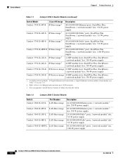
...module; blank module (see Table 1-3 on page 1-6). 2. You can upgrade to 30 W per port). 3. Table 1-2 Catalyst 3560-X Switch Models Switch Part Number Catalyst 3560-X-24T-L LAN Base image Catalyst 3560-X-48T-L LAN Base image Catalyst 3560-X-24P-L LAN Base image Catalyst 3560-X-48P-L LAN Base image Catalyst 3560-X-48PF...-19593-02 Switch Models Chapter 1 Product Overview Table 1-1 Catalyst 3750-X Switch Models (continued) Switch Model Cisco IOS Image Catalyst 3750-X-48T-S IP Base image3 Catalyst 3750-X-24P-S IP Base image3 Catalyst 3750-X-48P-S IP Base image3 Catalyst ...
...module; blank module (see Table 1-3 on page 1-6). 2. You can upgrade to 30 W per port). 3. Table 1-2 Catalyst 3560-X Switch Models Switch Part Number Catalyst 3560-X-24T-L LAN Base image Catalyst 3560-X-48T-L LAN Base image Catalyst 3560-X-24P-L LAN Base image Catalyst 3560-X-48P-L LAN Base image Catalyst 3560-X-48PF...-19593-02 Switch Models Chapter 1 Product Overview Table 1-1 Catalyst 3750-X Switch Models (continued) Switch Model Cisco IOS Image Catalyst 3750-X-48T-S IP Base image3 Catalyst 3750-X-24P-S IP Base image3 Catalyst 3750-X-48P-S IP Base image3 Catalyst ...
Hardware Installation Guide
Page 13
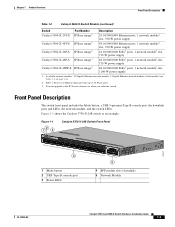
...3560-X-24T-S IP Base image3 Catalyst 3560-X-48T-S IP Base image3 Catalyst 3560-X-24P-S IP Base image3 Catalyst 3560-X-48P-S IP Base image3 Catalyst 3560-X-48PF-S IP Base image3 Description 24 10/100/1000 Ethernet ports, 1 network module1 slot, 350-W power supply 48 10/100/1000 Ethernet ports, 1 ... Panel Description The switch front panel includes the Mode button, a USB 5-pin mini-Type B console port, the downlink ports and LEDs, the network module, and the switch LEDs. Figure 1-1 shows the Catalyst 3750-X-24S switch as an example. PoE+ = Power over Ethernet plus (provides up to the...
...3560-X-24T-S IP Base image3 Catalyst 3560-X-48T-S IP Base image3 Catalyst 3560-X-24P-S IP Base image3 Catalyst 3560-X-48P-S IP Base image3 Catalyst 3560-X-48PF-S IP Base image3 Description 24 10/100/1000 Ethernet ports, 1 network module1 slot, 350-W power supply 48 10/100/1000 Ethernet ports, 1 ... Panel Description The switch front panel includes the Mode button, a USB 5-pin mini-Type B console port, the downlink ports and LEDs, the network module, and the switch LEDs. Figure 1-1 shows the Catalyst 3750-X-24S switch as an example. PoE+ = Power over Ethernet plus (provides up to the...

Hardware Installation Guide
Page 14
...The 10BASE-T traffic can use RJ-45 connectors with Ethernet pinouts. For information about the (uplink) SFP and SFP+ module slots on the network modules, see the "10/100/1000 Ethernet Port Connections" section on page 2-27 and Appendix B, "Connector and Cable Specifications...." Front Panel Description Chapter 1 Product Overview Figure 1-2 shows the Catalyst 3750-X-48P switch as an example. SFP+ modules are not supported. Catalyst 3750-X and 3560-X Switch Hardware Installation Guide 1-4 OL-19593-02 Figure 1-2 Catalyst 3750-X-48P Switch Front ...
...The 10BASE-T traffic can use RJ-45 connectors with Ethernet pinouts. For information about the (uplink) SFP and SFP+ module slots on the network modules, see the "10/100/1000 Ethernet Port Connections" section on page 2-27 and Appendix B, "Connector and Cable Specifications...." Front Panel Description Chapter 1 Product Overview Figure 1-2 shows the Catalyst 3750-X-48P switch as an example. SFP+ modules are not supported. Catalyst 3750-X and 3560-X Switch Hardware Installation Guide 1-4 OL-19593-02 Figure 1-2 Catalyst 3750-X-48P Switch Front ...

Hardware Installation Guide
Page 15
...Guide 1-5 When the switch internal power supply module(s) cannot support the total load, StackPower configurations allow the switch to leverage power available from other switches (only Catalyst 3750-X switches) • Configurable support for Cisco intelligent power management, including enhanced power negotiation,..., and per-port power policing Depending on the installed power supply modules, each port can deliver up to 30 W) • Support for Cisco enhanced PoE • Support for prestandard Cisco powered devices • Configuration for the power supply matrix that provides...
...Guide 1-5 When the switch internal power supply module(s) cannot support the total load, StackPower configurations allow the switch to leverage power available from other switches (only Catalyst 3750-X switches) • Configurable support for Cisco intelligent power management, including enhanced power negotiation,..., and per-port power policing Depending on the installed power supply modules, each port can deliver up to 30 W) • Support for Cisco enhanced PoE • Support for prestandard Cisco powered devices • Configuration for the power supply matrix that provides...

Hardware Installation Guide
Page 16
... 3560-X Switch Hardware Installation Guide 1-6 OL-19593-02 The four slots are not supported. When the SFP module in Slot 1 is shutdown, loses link, or is first inserted in the 1-Gigabit network module, the SFP+ module does not operate, and the switch logs an error message. The same precedence applies to the Configuring...
... 3560-X Switch Hardware Installation Guide 1-6 OL-19593-02 The four slots are not supported. When the SFP module in Slot 1 is shutdown, loses link, or is first inserted in the 1-Gigabit network module, the SFP+ module does not operate, and the switch logs an error message. The same precedence applies to the Configuring...

Hardware Installation Guide
Page 17
... fiber-optic connections or RJ-45 connectors for SMF, 1300 nm (DOM)4 OL-19593-02 Catalyst 3750-X and 3560-X Switch Hardware Installation Guide 1-7 Table 1-4 Supported Cisco SFP Modules Part Number GLC-GE-100FX=1,2,3 GLC-LH-SM= GLC-SX-MM= GLC-T=1, 3 GLC-ZX-SM= GLC-BX-D=1 GLC-BX-U=1 CWDM-SFP-1470= CWDM-SFP...
... fiber-optic connections or RJ-45 connectors for SMF, 1300 nm (DOM)4 OL-19593-02 Catalyst 3750-X and 3560-X Switch Hardware Installation Guide 1-7 Table 1-4 Supported Cisco SFP Modules Part Number GLC-GE-100FX=1,2,3 GLC-LH-SM= GLC-SX-MM= GLC-T=1, 3 GLC-ZX-SM= GLC-BX-D=1 GLC-BX-U=1 CWDM-SFP-1470= CWDM-SFP...

Hardware Installation Guide
Page 18
Front Panel Description Chapter 1 Product Overview Table 1-4 Supported Cisco SFP Modules (continued) Part Number DWDM-SFP-3033= DWDM-SFP-3112= DWDM-SFP-3190= DWDM-SFP-3268= DWDM-SFP-3346= DWDM-SFP-3425= DWDM-SFP-3504= DWDM-...
Front Panel Description Chapter 1 Product Overview Table 1-4 Supported Cisco SFP Modules (continued) Part Number DWDM-SFP-3033= DWDM-SFP-3112= DWDM-SFP-3190= DWDM-SFP-3268= DWDM-SFP-3346= DWDM-SFP-3425= DWDM-SFP-3504= DWDM-...

Hardware Installation Guide
Page 19
...the switch LEDs to select a port mode. For cable specifications, see your SFP module documentation and the "Installing SFP and SFP+ Modules" section on the C3KX-SM-10G 3. DOM = digital optical monitoring. Table 1-5 Supported Cisco SFP+ Modules Part Number SFP-10G-LR= SFP-10G-SR= SFP-10G-LRM= SFP-H10GB-...CU1M= SFP-H10GB-CU3M= SFP-H10GB-CU5M= Description 10 GBASE LR SFP+ transceiver module for SMF, 1350 nm, LC duplex connector 10 GBASE SR SFP...
...the switch LEDs to select a port mode. For cable specifications, see your SFP module documentation and the "Installing SFP and SFP+ Modules" section on the C3KX-SM-10G 3. DOM = digital optical monitoring. Table 1-5 Supported Cisco SFP+ Modules Part Number SFP-10G-LR= SFP-10G-SR= SFP-10G-LRM= SFP-H10GB-...CU1M= SFP-H10GB-CU3M= SFP-H10GB-CU5M= Description 10 GBASE LR SFP+ transceiver module for SMF, 1350 nm, LC duplex connector 10 GBASE SR SFP...

Hardware Installation Guide
Page 20
... during power-on self-test (POST), see the "Diagnosing Problems" section on . Only switches with one of the following: • Network module (non-traffic-related) • Power supply • Fan module System is receiving power but is not powered on page 4-1. 1-10 Catalyst 3750-X and 3560-X Switch Hardware Installation Guide OL-19593...
... during power-on self-test (POST), see the "Diagnosing Problems" section on . Only switches with one of the following: • Network module (non-traffic-related) • Power supply • Fan module System is receiving power but is not powered on page 4-1. 1-10 Catalyst 3750-X and 3560-X Switch Hardware Installation Guide OL-19593...
Hardware Installation Guide
Page 21
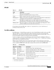
For information about the XPS 2200, see the Cisco eXpandable Power System 2200 Hardware Installation Guide on page 1-14. This is not installed. The stack master status. PoE+ port power The PoE+ port status. 1. ... Description STAT Port status The port status. Port LEDs and Modes Each Ethernet port, 1-Gigabit Ethernet module slot, and 10-Gigabit Ethernet module slot has a port LED. See the "Stack LED (Catalyst 3750-X)" section on Cisco.com. See the XPS 2200 documentation for information about the individual ports. DUPLX MAST1 STACK1 Port duplex...
For information about the XPS 2200, see the Cisco eXpandable Power System 2200 Hardware Installation Guide on page 1-14. This is not installed. The stack master status. PoE+ port power The PoE+ port status. 1. ... Description STAT Port status The port status. Port LEDs and Modes Each Ethernet port, 1-Gigabit Ethernet module slot, and 10-Gigabit Ethernet module slot has a port LED. See the "Stack LED (Catalyst 3750-X)" section on Cisco.com. See the XPS 2200 documentation for information about the individual ports. DUPLX MAST1 STACK1 Port duplex...

Hardware Installation Guide
Page 22
... a port is not the stack master. SPEED 10/100/1000/SFP ports Off Port is not operating. Stack member number. Link present, no activity. Network module slots Off Port is operating at 1000 Mb/s. Green Member numbers of Switch LED Colors in Different Modes Port Mode Port LED Color Meaning STAT...
... a port is not the stack master. SPEED 10/100/1000/SFP ports Off Port is not operating. Stack member number. Link present, no activity. Network module slots Off Port is operating at 1000 Mb/s. Green Member numbers of Switch LED Colors in Different Modes Port Mode Port LED Color Meaning STAT...

Hardware Installation Guide
Page 26
...19593-02 Front Panel Description Chapter 1 Product Overview Network Module LEDs Figure 1-5 Network Module LEDs (10-Gigabit Network Module Shown) 253212 37 38 39 40 41 42 43 ...4C4ataly4s5t 46 3750-X 47 48 PoE+48 C3KX-NM-10G NMEOTWDUOLREK G1 G2/TE1 G3 G4/TE2 1234 1 G1 LED 2 G2/TE1 LED 3 G3 LED 4 G4/TE2 LED Table 1-14 Network Module... LEDs Color Off Green Blinking green Blinking amber Network Module Link Status Link is off due to a fault or ...
...19593-02 Front Panel Description Chapter 1 Product Overview Network Module LEDs Figure 1-5 Network Module LEDs (10-Gigabit Network Module Shown) 253212 37 38 39 40 41 42 43 ...4C4ataly4s5t 46 3750-X 47 48 PoE+48 C3KX-NM-10G NMEOTWDUOLREK G1 G2/TE1 G3 G4/TE2 1234 1 G1 LED 2 G2/TE1 LED 3 G3 LED 4 G4/TE2 LED Table 1-14 Network Module... LEDs Color Off Green Blinking green Blinking amber Network Module Link Status Link is off due to a fault or ...

Hardware Installation Guide
Page 27
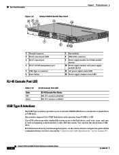
... port, a USB Type A connector, two StackWise connectors (only Catalyst 3750-X switches), two fan modules, an XPS 2200 connector, a StackPower connector (only Catalyst 3750-X switches), and two power supply module slots. Figure 1-7 Catalyst 3750-X Switch Rear Panel 235 47 1 CONSOLE STACK 1 AUX RESET STACK...management port 5 USB Type A connector 6 Stack cable connectors 7 Reset button 8 Fan modules 9 StackPower or XPS 2200 connector 10 StackPower connector 11 Power supply modules (AC power supply modules shown) 12 AC power (input) status LED 13 Power supply (output) status LED OL...
... port, a USB Type A connector, two StackWise connectors (only Catalyst 3750-X switches), two fan modules, an XPS 2200 connector, a StackPower connector (only Catalyst 3750-X switches), and two power supply module slots. Figure 1-7 Catalyst 3750-X Switch Rear Panel 235 47 1 CONSOLE STACK 1 AUX RESET STACK...management port 5 USB Type A connector 6 Stack cable connectors 7 Reset button 8 Fan modules 9 StackPower or XPS 2200 connector 10 StackPower connector 11 Power supply modules (AC power supply modules shown) 12 AC power (input) status LED 13 Power supply (output) status LED OL...
Hardware Installation Guide
Page 28
... 4 RJ-45 10/100 management port 5 USB Type A connector 6 Reset button 7 Fan modules 8 XPS 2200 connector 9 Power supply module slot (blank module shown) 10 Power supply module (AC power supply module shown) 11 AC power (input) status LED 12 Power supply (output) status LED RJ-45... Console Port LED Table 1-15 Color Off Green RJ-45 Console Port LED RJ-45 Console Port Status RS-232 console is enabled. The interface supports Cisco...
... 4 RJ-45 10/100 management port 5 USB Type A connector 6 Reset button 7 Fan modules 8 XPS 2200 connector 9 Power supply module slot (blank module shown) 10 Power supply module (AC power supply module shown) 11 AC power (input) status LED 12 Power supply (output) status LED RJ-45... Console Port LED Table 1-15 Color Off Green RJ-45 Console Port LED RJ-45 Console Port Status RS-232 console is enabled. The interface supports Cisco...


