
Installation Guide
Page 12
Appendix A, "Technical Specifications," lists the physical and environmental specifications for installing a switch on a rack, wall, table, or shelf. Organization Preface Organization This guide is organized into the following... the switch LEDs. Examples use these conventions: • Terminal sessions and system displays are in screen font. • Information you are in angle brackets (< >). Catalyst 3500 Series XL Hardware Installation Guide xii 78-6456-04 Appendix B, "Connector and Cable Specifications," describes the connectors, cables, and adapters that might arise when...
Appendix A, "Technical Specifications," lists the physical and environmental specifications for installing a switch on a rack, wall, table, or shelf. Organization Preface Organization This guide is organized into the following... the switch LEDs. Examples use these conventions: • Terminal sessions and system displays are in screen font. • Information you are in angle brackets (< >). Catalyst 3500 Series XL Hardware Installation Guide xii 78-6456-04 Appendix B, "Connector and Cable Specifications," describes the connectors, cables, and adapters that might arise when...
Installation Guide
Page 21
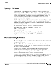
... 2 8446 7411 (Australia: 1 800 805 227) EMEA: +32 2 704 55 55 USA: 1 800 553-2447 For a complete listing of Cisco TAC contacts, go to this URL: http://www.cisco.com/warp/public/687/Directory/DirTAC.shtml TAC Case Priority Definitions To ensure that all necessary resources around the clock to... to help keep your case will commit resources during normal business hours to satisfactory levels. 78-6456-04 Catalyst 3500 Series XL Hardware Installation Guide xxi You and Cisco will commit all cases are negatively affected by inadequate performance of your situation, the TAC Case Open Tool ...
... 2 8446 7411 (Australia: 1 800 805 227) EMEA: +32 2 704 55 55 USA: 1 800 553-2447 For a complete listing of Cisco TAC contacts, go to this URL: http://www.cisco.com/warp/public/687/Directory/DirTAC.shtml TAC Case Priority Definitions To ensure that all necessary resources around the clock to... to help keep your case will commit resources during normal business hours to satisfactory levels. 78-6456-04 Catalyst 3500 Series XL Hardware Installation Guide xxi You and Cisco will commit all cases are negatively affected by inadequate performance of your situation, the TAC Case Open Tool ...
Installation Guide
Page 23
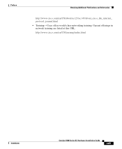
Current offerings in network training are listed at this URL: http://www.cisco.com/en/US/learning/index.html 78-6456-04 Catalyst 3500 Series XL Hardware Installation Guide xxiii Preface Obtaining Additional Publications and Information http://www.cisco.com/en/US/about/ac123/ac147/about_cisco_the_internet_ protocol_journal.html • Training-Cisco offers world-class networking training.
Current offerings in network training are listed at this URL: http://www.cisco.com/en/US/learning/index.html 78-6456-04 Catalyst 3500 Series XL Hardware Installation Guide xxiii Preface Obtaining Additional Publications and Information http://www.cisco.com/en/US/about/ac123/ac147/about_cisco_the_internet_ protocol_journal.html • Training-Cisco offers world-class networking training.

Installation Guide
Page 25
...Catalyst 3524-PWR XL switch is its ability to provide inline power to Cisco IP Phones. (Phone adapters are stackable 10/100 Ethernet switches to the Catalyst... 3524-PWR XL 10/100 switch ports.) Figure 1-1 shows the switch models in different network topologies Features The Catalyst 3500 series XL switches-also referred to as Catalyst...Product Overview This chapter provides the following topics that describe the Catalyst 3500 series XL switches: • Switch features • Descriptions of the front...
...Catalyst 3524-PWR XL switch is its ability to provide inline power to Cisco IP Phones. (Phone adapters are stackable 10/100 Ethernet switches to the Catalyst... 3524-PWR XL 10/100 switch ports.) Figure 1-1 shows the switch models in different network topologies Features The Catalyst 3500 series XL switches-also referred to as Catalyst...Product Overview This chapter provides the following topics that describe the Catalyst 3500 series XL switches: • Switch features • Descriptions of the front...

Installation Guide
Page 38
... is not functioning properly. System is functioning properly. Table 1-3 lists the LED colors and their meanings. For information on the System LED colors during POST, see the "Powering On the Switch and Running POST" section on . Front-Panel Description Figure 1-12 Catalyst 3548 XL LEDs Port LEDs Chapter 1 Product Overview SYSTEM RPS... System LED shows whether the system is receiving power and is operating normally. System is receiving power but is not powered on page 2-17. 1-14 Catalyst 3500 Series XL Hardware Installation Guide 78-6456-04
... is not functioning properly. System is functioning properly. Table 1-3 lists the LED colors and their meanings. For information on the System LED colors during POST, see the "Powering On the Switch and Running POST" section on . Front-Panel Description Figure 1-12 Catalyst 3548 XL LEDs Port LEDs Chapter 1 Product Overview SYSTEM RPS... System LED shows whether the system is receiving power and is operating normally. System is receiving power but is not powered on page 2-17. 1-14 Catalyst 3500 Series XL Hardware Installation Guide 78-6456-04

Installation Guide
Page 39
...section on the bottom of the power supplies in the RPS could have failed. Note The Cisco RPS 300 (model PWR300-AC-RPS) supports the Catalyst 3524-PWR XL switch. 78-6456-04 Catalyst 3500 Series XL Hardware Installation Guide 1-15 Table 1-4 RPS LED for RPS revision level Z3... or later. If the switch power supply fails, the switch powers down , or a fan on . RPS is not a recommended configuration. Note This is connected but not functioning properly. Table 1-4 and Table 1-5 list...
...section on the bottom of the power supplies in the RPS could have failed. Note The Cisco RPS 300 (model PWR300-AC-RPS) supports the Catalyst 3524-PWR XL switch. 78-6456-04 Catalyst 3500 Series XL Hardware Installation Guide 1-15 Table 1-4 RPS LED for RPS revision level Z3... or later. If the switch power supply fails, the switch powers down , or a fan on . RPS is not a recommended configuration. Note This is connected but not functioning properly. Table 1-4 and Table 1-5 list...

Installation Guide
Page 65
... (MSZEN55022). For specific cable lengths, refer to the documents that came with the GigaStack GBIC. • Operating environment is within the ranges listed in Appendix A, "Technical Specifications." 78-6456-04 Catalyst 3500 Series XL Hardware Installation Guide 2-7 Class A equipment is designed for typical commercial establishments for Installation Warning This equipment is a class...
... (MSZEN55022). For specific cable lengths, refer to the documents that came with the GigaStack GBIC. • Operating environment is within the ranges listed in Appendix A, "Technical Specifications." 78-6456-04 Catalyst 3500 Series XL Hardware Installation Guide 2-7 Class A equipment is designed for typical commercial establishments for Installation Warning This equipment is a class...
Installation Guide
Page 87
... a mapping for its ports. Chapter 2 Installing and Starting Up the Switch Default Configuration Settings Using BOOTP You can operate with a list of physical MAC addresses and corresponding IP addresses must be set , but the saved configuration in Flash memory is set up on the... the write memory command. Default Configuration Settings After you assign IP information, the switch can use BOOTP to assign IP information to a Catalyst 3500 XL switch. The IP information is mandatory, and the subnet mask and the default gateway, which are optional. Other optional information...
... a mapping for its ports. Chapter 2 Installing and Starting Up the Switch Default Configuration Settings Using BOOTP You can operate with a list of physical MAC addresses and corresponding IP addresses must be set , but the saved configuration in Flash memory is set up on the... the write memory command. Default Configuration Settings After you assign IP information, the switch can use BOOTP to assign IP information to a Catalyst 3500 XL switch. The IP information is mandatory, and the subnet mask and the default gateway, which are optional. Other optional information...
Installation Guide
Page 92
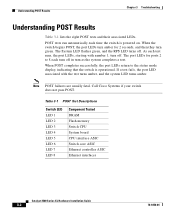
...port LEDs for 2 seconds, and then they turn as the system completes a test. Call Cisco Systems if your switch does not pass POST. Table 3-1 POST Test Descriptions Switch LED LED... Tested DRAM Flash memory Switch CPU System board CPU interface ASIC Switch core ASIC Ethernet controller ASIC Ethernet interfaces Catalyst 3500 Series XL Hardware Installation Guide 3-2 78-6456-04 POST tests run automatically each time the switch is ... Results Chapter 3 Troubleshooting Understanding POST Results Table 3-1 lists the eight POST tests and their associated LEDs. Note POST failures are usually fatal.
...port LEDs for 2 seconds, and then they turn as the system completes a test. Call Cisco Systems if your switch does not pass POST. Table 3-1 POST Test Descriptions Switch LED LED... Tested DRAM Flash memory Switch CPU System board CPU interface ASIC Switch core ASIC Ethernet controller ASIC Ethernet interfaces Catalyst 3500 Series XL Hardware Installation Guide 3-2 78-6456-04 POST tests run automatically each time the switch is ... Results Chapter 3 Troubleshooting Understanding POST Results Table 3-1 lists the eight POST tests and their associated LEDs. Note POST failures are usually fatal.

Installation Guide
Page 97
... A P P E N D I X Technical Specifications 78-6456-04 Table A-1, Table A-2, and Table A-3, list the technical specifications for the Catalyst 3508G XL Switch Environmental Ranges Operating temperature Storage temperature Operating humidity Operating altitude Storage altitude Power Requirements AC input voltage ...12V @3A 82.2W 280 Btus per hour 12 lb (5.45 kg) 1.75 x 16 x 17.5 in. (4.45 x 40.46 x 44.45 cm) Catalyst 3500 Series XL Hardware Installation Guide A-1 Table A-1 Technical Specifications for the Catalyst 3500 series XL switches. Table A-4 lists the regulatory agency approvals.
... A P P E N D I X Technical Specifications 78-6456-04 Table A-1, Table A-2, and Table A-3, list the technical specifications for the Catalyst 3508G XL Switch Environmental Ranges Operating temperature Storage temperature Operating humidity Operating altitude Storage altitude Power Requirements AC input voltage ...12V @3A 82.2W 280 Btus per hour 12 lb (5.45 kg) 1.75 x 16 x 17.5 in. (4.45 x 40.46 x 44.45 cm) Catalyst 3500 Series XL Hardware Installation Guide A-1 Table A-1 Technical Specifications for the Catalyst 3500 series XL switches. Table A-4 lists the regulatory agency approvals.

Installation Guide
Page 106
... DB-9 Pin 8 6 2 5 5 3 4 7 Console Device Signal CTS DSR RxD GND GND TxD DTR RTS Catalyst 3500 Series XL Hardware Installation Guide B-6 78-6456-04 Figure B-7 Connecting the Console Port to a PC PC Catalyst 3500 series XL switch 22003 RJ-45-to-RJ-45 rollover cable RJ-45-to-DB-9 adapter...Signal RJ-45 Pin RJ-45 Pin RTS 1 8 Not connected 2 7 TxD 3 6 GND 4 5 GND 5 4 RxD 6 3 Not connected 7 2 CTS 8 1 RJ-45-to a PC. Table B-1 lists the pinouts for the console port, the RJ-45-to-RJ-45 rollover cable, and the RJ-45-to a PC running terminal-emulation software. Cable...
... DB-9 Pin 8 6 2 5 5 3 4 7 Console Device Signal CTS DSR RxD GND GND TxD DTR RTS Catalyst 3500 Series XL Hardware Installation Guide B-6 78-6456-04 Figure B-7 Connecting the Console Port to a PC PC Catalyst 3500 series XL switch 22003 RJ-45-to-RJ-45 rollover cable RJ-45-to-DB-9 adapter...Signal RJ-45 Pin RJ-45 Pin RTS 1 8 Not connected 2 7 TxD 3 6 GND 4 5 GND 5 4 RxD 6 3 Not connected 7 2 CTS 8 1 RJ-45-to a PC. Table B-1 lists the pinouts for the console port, the RJ-45-to-RJ-45 rollover cable, and the RJ-45-to a PC running terminal-emulation software. Cable...
Installation Guide
Page 107
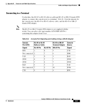
... to -DB-25 Terminal Adapter DB-25 Pin 5 6 3 7 7 2 20 4 Console Device Signal CTS DSR RxD GND GND TxD DTR RTS 78-6456-04 Catalyst 3500 Series XL Hardware Installation Guide B-7 Table B-2 Console Port Signaling and Cabling Using a DB-25 Adapter Console Port (DTE) RJ-45-to-RJ-45 Rollover... 8 Not connected 2 7 TxD 3 6 GND 4 5 GND 5 4 RxD 6 3 Not connected 7 2 CTS 8 1 RJ-45-to a terminal. Note The RJ-45-to -DB-25 female DTE adapter. Table B-2 lists the pinouts for the console port, the RJ-45-to-RJ-45 rollover cable, and the RJ-45-to -DB-25 female DTE adapter is...
... to -DB-25 Terminal Adapter DB-25 Pin 5 6 3 7 7 2 20 4 Console Device Signal CTS DSR RxD GND GND TxD DTR RTS 78-6456-04 Catalyst 3500 Series XL Hardware Installation Guide B-7 Table B-2 Console Port Signaling and Cabling Using a DB-25 Adapter Console Port (DTE) RJ-45-to-RJ-45 Rollover... 8 Not connected 2 7 TxD 3 6 GND 4 5 GND 5 4 RxD 6 3 Not connected 7 2 CTS 8 1 RJ-45-to a terminal. Note The RJ-45-to -DB-25 female DTE adapter. Table B-2 lists the pinouts for the console port, the RJ-45-to-RJ-45 rollover cable, and the RJ-45-to -DB-25 female DTE adapter is...
Installation Guide
Page 156
... 1-14 UTL 1-16, 1-18 lightning activity warning C-30 line power See inline power M management features and defaults 2-30 Mode button 1-11, 1-16 Mode label (on Catalyst 3548 XL only) 1-16 models, switch 1-2 mounting, table or desk 2-17 mounting brackets 2-9 attaching 2-11, 2-15 rack-mount 2-13 wall-mount 2-16 N network configuration... examples 1-25 network redundancy values 2-30 noise, electrical 2-8 no on/off switch warning C-25 O overtemperature warning C-16 P packing list 2-8 IN-4 Catalyst 3500 Series XL Hardware Installation Guide 78-6456-04
... 1-14 UTL 1-16, 1-18 lightning activity warning C-30 line power See inline power M management features and defaults 2-30 Mode button 1-11, 1-16 Mode label (on Catalyst 3548 XL only) 1-16 models, switch 1-2 mounting, table or desk 2-17 mounting brackets 2-9 attaching 2-11, 2-15 rack-mount 2-13 wall-mount 2-16 N network configuration... examples 1-25 network redundancy values 2-30 noise, electrical 2-8 no on/off switch warning C-25 O overtemperature warning C-16 P packing list 2-8 IN-4 Catalyst 3500 Series XL Hardware Installation Guide 78-6456-04