Hardware Installation Guide
Page 2
...does not imply a partnership relationship between Cisco and any interference to one of Cisco and/or its peripheral devices. All rights reserved. These specifications are the property of the UNIX operating system. Modifying the equipment without Cisco's written authorization may result in the equipment... has been tested and found to use of the FCC rules. THE SPECIFICATIONS AND INFORMATION REGARDING THE PRODUCTS IN THIS MANUAL ARE SUBJECT TO CHANGE WITHOUT NOTICE. IN NO EVENT SHALL CISCO OR ITS SUPPLIERS BE LIABLE FOR ANY INDIRECT, SPECIAL, CONSEQUENTIAL, OR INCIDENTAL...
...does not imply a partnership relationship between Cisco and any interference to one of Cisco and/or its peripheral devices. All rights reserved. These specifications are the property of the UNIX operating system. Modifying the equipment without Cisco's written authorization may result in the equipment... has been tested and found to use of the FCC rules. THE SPECIFICATIONS AND INFORMATION REGARDING THE PRODUCTS IN THIS MANUAL ARE SUBJECT TO CHANGE WITHOUT NOTICE. IN NO EVENT SHALL CISCO OR ITS SUPPLIERS BE LIABLE FOR ANY INDIRECT, SPECIAL, CONSEQUENTIAL, OR INCIDENTAL...

Hardware Installation Guide
Page 6
.../100 and 10/100/1000 Ports B-1 SFP Module Ports B-2 Dual-Purpose Ports B-3 Console Port B-3 Cable and Adapter Specifications B-4 SFP Module Cable Specifications B-4 Two Twisted-Pair Cable Pinouts B-5 Four Twisted-Pair Cable Pinouts for 1000BASE-T Ports B-6 Identifying a Crossover Cable B-6 Adapter Pinouts B-7 Connecting to DC Power C-1 Connecting to DC ...
.../100 and 10/100/1000 Ports B-1 SFP Module Ports B-2 Dual-Purpose Ports B-3 Console Port B-3 Cable and Adapter Specifications B-4 SFP Module Cable Specifications B-4 Two Twisted-Pair Cable Pinouts B-5 Four Twisted-Pair Cable Pinouts for 1000BASE-T Ports B-6 Identifying a Crossover Cable B-6 Adapter Pinouts B-7 Connecting to DC Power C-1 Connecting to DC ...

Hardware Installation Guide
Page 19
... for the cables are described in Appendix B, "Connector and Cable Specifications." • You can control whether or not a PoE port automatically provides power when an IP phone or an access point is connected. • You can connect a Cisco IP Phone or Cisco Aironet Access Point to a Catalyst 3560 PoE switch 10/100 or...
... for the cables are described in Appendix B, "Connector and Cable Specifications." • You can control whether or not a PoE port automatically provides power when an IP phone or an access point is connected. • You can connect a Cisco IP Phone or Cisco Aironet Access Point to a Catalyst 3560 PoE switch 10/100 or...

Hardware Installation Guide
Page 20
... 1-10 Catalyst 3560 Switch Hardware Installation Guide OL-6337-07 Front Panel Description Chapter 1 Product Overview Many legacy powered devices, including older Cisco IP phones and access points that first links up. SFP Modules The switch uses Gigabit Ethernet SFP modules to the switches by a crossover ..." section on for your switch software. The dual front ends are field-replaceable, providing uplink interfaces when inserted in the "SFP Module Cable Specifications" section on page B-4. Each port is on page 2-18 for the latest list of the pair at each end (see Figure 1-11)....
... 1-10 Catalyst 3560 Switch Hardware Installation Guide OL-6337-07 Front Panel Description Chapter 1 Product Overview Many legacy powered devices, including older Cisco IP phones and access points that first links up. SFP Modules The switch uses Gigabit Ethernet SFP modules to the switches by a crossover ..." section on for your switch software. The dual front ends are field-replaceable, providing uplink interfaces when inserted in the "SFP Module Cable Specifications" section on page B-4. Each port is on page 2-18 for the latest list of the pair at each end (see Figure 1-11)....

Hardware Installation Guide
Page 29
... products, including compatibility matrixes listing the supported RPS for each Catalyst 3560 switch, see the "Connector and Cable Specifications" section on page B-1. The Cisco RPS 2300 has two output levels: -52 V and 12 V. You can order a kit (part number ACS-DSBUASYN=) containing that ...supports six network switches and provides power to one failed switch at a time. Cisco RPS 675 The Cisco 675 RPS is a redundant power system that supports six network devices and provides power to one or two failed switches at a time...
... products, including compatibility matrixes listing the supported RPS for each Catalyst 3560 switch, see the "Connector and Cable Specifications" section on page B-1. The Cisco RPS 2300 has two output levels: -52 V and 12 V. You can order a kit (part number ACS-DSBUASYN=) containing that ...supports six network switches and provides power to one failed switch at a time. Cisco RPS 675 The Cisco 675 RPS is a redundant power system that supports six network devices and provides power to one or two failed switches at a time...

Hardware Installation Guide
Page 37
...Systems (NEBS) standard for electromagnetic compatibility and safety, connect the ethernet cables only to 328 feet (100 meters). • The cables meet the specifications in a closed or multirack assembly, the temperature around the unit does not exceed 113°F (45°C). The rear-panel power connector is within...; Airflow around the switch and through the vents is installed in Table B-1 on page B-4, which lists the cable specifications for 1000BASE-X and 100BASE-X SFP modules for unrestricted cabling. - and 48-Port Switches) Statement 371-Power Cable and AC Adapter Preparing ...
...Systems (NEBS) standard for electromagnetic compatibility and safety, connect the ethernet cables only to 328 feet (100 meters). • The cables meet the specifications in a closed or multirack assembly, the temperature around the unit does not exceed 113°F (45°C). The rear-panel power connector is within...; Airflow around the switch and through the vents is installed in Table B-1 on page B-4, which lists the cable specifications for 1000BASE-X and 100BASE-X SFP modules for unrestricted cabling. - and 48-Port Switches) Statement 371-Power Cable and AC Adapter Preparing ...
Hardware Installation Guide
Page 47
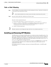
...modules are not being used, replace the dust covers on page B-4 for cable stipulations for reliable communications, the cable must match the wave-length specifications on the other end of the cable, and for SFP connections. You can use the CLI setup program, see the SFP module documentation. ... modules. Connect to a 10/100 or 10/100/1000 port, and run Express Setup. After the switch is encoded with security information, which Cisco uses to the bottom of the switch. OL-6337-07 Catalyst 3560 Switch Hardware Installation Guide 2-15 See the "Verifying Switch Operation" section on...
...modules are not being used, replace the dust covers on page B-4 for cable stipulations for reliable communications, the cable must match the wave-length specifications on the other end of the cable, and for SFP connections. You can use the CLI setup program, see the SFP module documentation. ... modules. Connect to a 10/100 or 10/100/1000 port, and run Express Setup. After the switch is encoded with security information, which Cisco uses to the bottom of the switch. OL-6337-07 Catalyst 3560 Switch Hardware Installation Guide 2-15 See the "Verifying Switch Operation" section on...
Hardware Installation Guide
Page 52
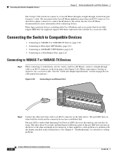
...; Connecting to a Dual-Purpose Port, page 2-23 Connecting to 10BASE-T or 100BASE-TX Devices Step 1 When connecting to workstations, servers, routers, and Cisco IP Phones, connect a straight-through , twisted four-pair Category 5 cable. See Chapter 4, "Troubleshooting," for more than one RJ-45 connector. Connecting ...connect the IP phone to a Cisco IP Phone through a straight-through cable to an RJ-45 connector on the front panel. (See Figure 2-18.) When connecting to switches or repeaters, use a crossover cable. (See the "Cable and Adapter Specifications" section on when both the ...
...; Connecting to a Dual-Purpose Port, page 2-23 Connecting to 10BASE-T or 100BASE-TX Devices Step 1 When connecting to workstations, servers, routers, and Cisco IP Phones, connect a straight-through , twisted four-pair Category 5 cable. See Chapter 4, "Troubleshooting," for more than one RJ-45 connector. Connecting ...connect the IP phone to a Cisco IP Phone through a straight-through cable to an RJ-45 connector on the front panel. (See Figure 2-18.) When connecting to switches or repeaters, use a crossover cable. (See the "Cable and Adapter Specifications" section on when both the ...
Hardware Installation Guide
Page 53
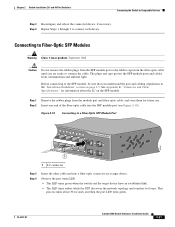
See Appendix B, "Connector and Cable Specifications," for information about 30 seconds, and then the port LED turns green. Figure 2-19 Connecting to a Fiber-Optic SFP Module Port 40 41 42 43 ...
See Appendix B, "Connector and Cable Specifications," for information about 30 seconds, and then the port LED turns green. Figure 2-19 Connecting to a Fiber-Optic SFP Module Port 40 41 42 43 ...

Hardware Installation Guide
Page 57
... start your switch installation, including how to Compatible Devices" section on self-test (POST) that ensures proper operation. Note This chapter describes the installation information specific to install the switch.
... start your switch installation, including how to Compatible Devices" section on self-test (POST) that ensures proper operation. Note This chapter describes the installation information specific to install the switch.
Hardware Installation Guide
Page 61
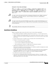
... them side by side. • You have allowed at least 3 inches (7.6 cm) of clearance on the top of clearance above each switch in Appendix A, "Technical Specifications." • Airflow around the switch and through the vents is within the ranges listed in the rack. • Clearance to the nearest rack metal hardware...
... them side by side. • You have allowed at least 3 inches (7.6 cm) of clearance on the top of clearance above each switch in Appendix A, "Technical Specifications." • Airflow around the switch and through the vents is within the ranges listed in the rack. • Clearance to the nearest rack metal hardware...
Hardware Installation Guide
Page 62
...decibel (dB) or 10-dB inline optical attenuator between the fiber-optic cable plant and the receiving port on page B-4, which lists the cable specifications for 1000BASE-X and 100BASE-X SFP modules for this compact model: - You must install this equipment to install the switch: • Number-2 Phillips...IEC) IP-20 This applies to insert an inline optical attenuator in a system malfunction. Cable locks are equipped with that is away from Cisco. You can order a kit (part number ACS-DSBUASYN=) with cooling mechanisms, such as radios, power lines, and fluorescent lighting fixtures. ...
...decibel (dB) or 10-dB inline optical attenuator between the fiber-optic cable plant and the receiving port on page B-4, which lists the cable specifications for 1000BASE-X and 100BASE-X SFP modules for this compact model: - You must install this equipment to install the switch: • Number-2 Phillips...IEC) IP-20 This applies to insert an inline optical attenuator in a system malfunction. Cable locks are equipped with that is away from Cisco. You can order a kit (part number ACS-DSBUASYN=) with cooling mechanisms, such as radios, power lines, and fluorescent lighting fixtures. ...
Hardware Installation Guide
Page 79
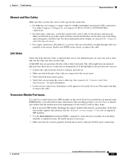
...and port type. See Appendix B, "Connector and Cable Specifications." Sometimes a cable appears to be seated, but the other side does not have link. Disconnect and then reconnect the cable. This encoding provides a way for Cisco to function at a marginal level. Verify that the ...causes it to identify and validate that this module supports this platform. for more information about cabling, see Appendix B, "Connector and Cable Specifications." • For copper connections, determine if a crossover cable was used when a straight-through cable was required or the reverse. For ...
...and port type. See Appendix B, "Connector and Cable Specifications." Sometimes a cable appears to be seated, but the other side does not have link. Disconnect and then reconnect the cable. This encoding provides a way for Cisco to function at a marginal level. Verify that the ...causes it to identify and validate that this module supports this platform. for more information about cabling, see Appendix B, "Connector and Cable Specifications." • For copper connections, determine if a crossover cable was used when a straight-through cable was required or the reverse. For ...
Hardware Installation Guide
Page 81
... want to manually set to full duplex with an incorrect IP address, you have configured a new switch with no autonegotiation. See Appendix B, "Connector and Cable Specifications," for cabling guidelines. Clearing the Switch IP Address and Configuration If you can adjust itself even if the connected port does not autonegotiate. Continue holding...
... want to manually set to full duplex with an incorrect IP address, you have configured a new switch with no autonegotiation. See Appendix B, "Connector and Cable Specifications," for cabling guidelines. Clearing the Switch IP Address and Configuration If you can adjust itself even if the connected port does not autonegotiate. Continue holding...
Hardware Installation Guide
Page 85
... for all Catalyst 3560 Switches • Table A-2 on page A-2, Technical Specifications for the Catalyst 3560-24PS Switch • Table A-3 on page A-2, Specifications for the Catalyst 3560-48PS Switch • Table A-4 on page A-3, Specifications for the Catalyst 3560-24TS-S Switch • Table A-5 on page A-3, Specifications for the Catalyst 3560-48TS-S Switch • Table A-6 on page...
... for all Catalyst 3560 Switches • Table A-2 on page A-2, Technical Specifications for the Catalyst 3560-24PS Switch • Table A-3 on page A-2, Specifications for the Catalyst 3560-48PS Switch • Table A-4 on page A-3, Specifications for the Catalyst 3560-24TS-S Switch • Table A-5 on page A-3, Specifications for the Catalyst 3560-48TS-S Switch • Table A-6 on page...
Hardware Installation Guide
Page 86
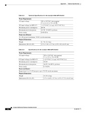
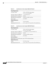
Appendix A Technical Specifications Table A-2 Technical Specifications for the Catalyst 3560-24PS Switch Power Requirements AC input voltage 100 to 240 VAC (autoranging) 5.5 A to 2.8 A, 50 to 60 Hz DC input voltage for ....4 W per port maximum, 370 W switch maximum Physical Dimensions Weight 11.3 lb (5.14 kg) Dimensions (H x D x W) 1.73 x 11.81 x 17.5 in. (4.39 x 30 x 44.45 cm) Table A-3 Specifications for the Catalyst 3560-48PS Switch Power Requirements AC input voltage 100 to 240 VAC (autoranging) 5.5 to 2.8 A, 50 to 60 Hz DC input voltages for...
Appendix A Technical Specifications Table A-2 Technical Specifications for the Catalyst 3560-24PS Switch Power Requirements AC input voltage 100 to 240 VAC (autoranging) 5.5 A to 2.8 A, 50 to 60 Hz DC input voltage for ....4 W per port maximum, 370 W switch maximum Physical Dimensions Weight 11.3 lb (5.14 kg) Dimensions (H x D x W) 1.73 x 11.81 x 17.5 in. (4.39 x 30 x 44.45 cm) Table A-3 Specifications for the Catalyst 3560-48PS Switch Power Requirements AC input voltage 100 to 240 VAC (autoranging) 5.5 to 2.8 A, 50 to 60 Hz DC input voltages for...
Hardware Installation Guide
Page 87
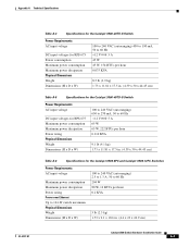
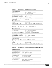
...A 45 W 45 W, 154 BTUs per hour 0.075 KVA 8.5 lb (3.9 kg) 1.73 x 11.81 x 17.5 in. (4.39 x 30 x 44.45 cm) Table A-5 Specifications for the Catalyst 3560-48TS-S Switch Power Requirements AC input voltage DC input voltages for RPS 675 Maximum power consumption Maximum power dissipation Power rating... A 65 W 65 W, 222 BTUs per hour 0.110 KVA 9.1 lb (4.1 kg) 1.73 x 11.81 x 17.5 in. (4.39 x 30 x 44.45 cm) Table A-6 Specifications for the Catalyst 3560-8PC and Catalyst 3560-12PC Switches Power Requirements AC input voltage Maximum power consumption Maximum power dissipation Power rating Power over...
...A 45 W 45 W, 154 BTUs per hour 0.075 KVA 8.5 lb (3.9 kg) 1.73 x 11.81 x 17.5 in. (4.39 x 30 x 44.45 cm) Table A-5 Specifications for the Catalyst 3560-48TS-S Switch Power Requirements AC input voltage DC input voltages for RPS 675 Maximum power consumption Maximum power dissipation Power rating... A 65 W 65 W, 222 BTUs per hour 0.110 KVA 9.1 lb (4.1 kg) 1.73 x 11.81 x 17.5 in. (4.39 x 30 x 44.45 cm) Table A-6 Specifications for the Catalyst 3560-8PC and Catalyst 3560-12PC Switches Power Requirements AC input voltage Maximum power consumption Maximum power dissipation Power rating Power over...
Hardware Installation Guide
Page 88
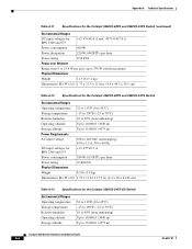
Appendix A Technical Specifications Table A-7 Specifications for the Catalyst 3560G-24TS Switch Power Requirements AC input voltage DC input voltages for RPS 675 Maximum power consumption Maximum power dissipation Power rating ... Hz +12 V @10.5 A 100 W 100 W, 314 BTUs per hour 0.10 KVA 12 lb (5.44 kg) 1.73 x 14.9 x 17.5 in. (4.39 x 37.8 x 44.45 cm) Table A-8 Specifications for the Catalyst 3560G-24PS Switch Power Requirements AC input voltage 100 to 240 VAC (autoranging) 4 to 8 A, 50 to 60 Hz DC input voltages for...
Appendix A Technical Specifications Table A-7 Specifications for the Catalyst 3560G-24TS Switch Power Requirements AC input voltage DC input voltages for RPS 675 Maximum power consumption Maximum power dissipation Power rating ... Hz +12 V @10.5 A 100 W 100 W, 314 BTUs per hour 0.10 KVA 12 lb (5.44 kg) 1.73 x 14.9 x 17.5 in. (4.39 x 37.8 x 44.45 cm) Table A-8 Specifications for the Catalyst 3560G-24PS Switch Power Requirements AC input voltage 100 to 240 VAC (autoranging) 4 to 8 A, 50 to 60 Hz DC input voltages for...
Hardware Installation Guide
Page 89
... W, 500 BTUs per hour 0.16 KVA 14 lb (6.4 kg) 1.73 x 16.1 x 17.5 in. (4.39 x 40.9 x 44.45 cm) Table A-10 Specifications for the Catalyst 3560G-48PS Switch Power Requirements AC input voltage 100 to 240 VAC (autoranging) 4 to 8 A, 50 to 60 Hz DC input voltages for... Weight 15.5 lb (7.03 kg) Dimensions (H x D x W) 1.73 x 16.1 x 17.5 in. (4.39 x 40.9 x 44.45 cm) Table A-11 Specifications for the Catalyst 3560V2-48PS and 3560V2-24PS Switch Environmental Ranges Operating temperature Storage temperature Relative humidity Operating altitude Storage altitude Power Requirements AC input...
... W, 500 BTUs per hour 0.16 KVA 14 lb (6.4 kg) 1.73 x 16.1 x 17.5 in. (4.39 x 40.9 x 44.45 cm) Table A-10 Specifications for the Catalyst 3560G-48PS Switch Power Requirements AC input voltage 100 to 240 VAC (autoranging) 4 to 8 A, 50 to 60 Hz DC input voltages for... Weight 15.5 lb (7.03 kg) Dimensions (H x D x W) 1.73 x 16.1 x 17.5 in. (4.39 x 40.9 x 44.45 cm) Table A-11 Specifications for the Catalyst 3560V2-48PS and 3560V2-24PS Switch Environmental Ranges Operating temperature Storage temperature Relative humidity Operating altitude Storage altitude Power Requirements AC input...
Hardware Installation Guide
Page 90
... Dimensions Weight 11.3 lb (5.1 kg) Dimensions (H x W x D) 1.73 x 17.5 x 11.8 in. (4.4 x 44.5 x 30.1 cm) Table A-12 Specifications for the Catalyst 3560V2-48TS and 3560V2-24TS Switch Environmental Ranges Operating temperature 32 to 113°F (0 to 45°C) Storage temperature -13 to 158... lb (3.9 kg) Dimensions (H x W x D) 1.73 x 11.81 x 17.5 in. (4.4 x 30 x 44.45 cm) Table A-13 Specifications for the Catalyst 3560V2-24TS-SD Switch Environmental Ranges Operating temperature Storage temperature Relative humidity Operating altitude Storage altitude 32 to 113°F (0 to 45...
... Dimensions Weight 11.3 lb (5.1 kg) Dimensions (H x W x D) 1.73 x 17.5 x 11.8 in. (4.4 x 44.5 x 30.1 cm) Table A-12 Specifications for the Catalyst 3560V2-48TS and 3560V2-24TS Switch Environmental Ranges Operating temperature 32 to 113°F (0 to 45°C) Storage temperature -13 to 158... lb (3.9 kg) Dimensions (H x W x D) 1.73 x 11.81 x 17.5 in. (4.4 x 30 x 44.45 cm) Table A-13 Specifications for the Catalyst 3560V2-24TS-SD Switch Environmental Ranges Operating temperature Storage temperature Relative humidity Operating altitude Storage altitude 32 to 113°F (0 to 45...
