
Hardware Installation Guide
Page 3
... 1-11 RPS LED 1-12 Port LEDs and Modes 1-13 Dual-Purpose Port LEDs 1-15 Cable Guard 1-15 Rear Panel Description 1-15 Internal Power Supply 1-18 DC Power Connector 1-18 Cisco RPS 1-19 Cisco RPS 2300 1-19 Cisco RPS 675 1-19 Console Port 1-19 Security Slots 1-20 Management Options 1-20 Catalyst 3560 Switch Hardware Installation Guide iii
... 1-11 RPS LED 1-12 Port LEDs and Modes 1-13 Dual-Purpose Port LEDs 1-15 Cable Guard 1-15 Rear Panel Description 1-15 Internal Power Supply 1-18 DC Power Connector 1-18 Cisco RPS 1-19 Cisco RPS 2300 1-19 Cisco RPS 675 1-19 Console Port 1-19 Security Slots 1-20 Management Options 1-20 Catalyst 3560 Switch Hardware Installation Guide iii

Hardware Installation Guide
Page 4
... T E R Network Configurations 1-21 Switch Installation (24- and 48-Port Switches) 2-1 Preparing for Installation 2-1 Warnings 2-2 Installation Guidelines 2-5 Box Contents 2-6 Tools and Equipment 2-6 Verifying Switch Operation 2-6 Powering Off the Switch 2-7 Installing the Switch 2-7 Rack-Mounting 2-7 Removing Screws from SFP Module Slots 2-17 Inserting and Removing the SFP Module Patch Cable 2-18 10...23 Where to the Switch for Installation 3-1 Warnings 3-2 Installation Guidelines 3-5 Equipment That You Supply 3-6 Catalyst 3560 Switch Hardware Installation Guide iv OL-6337-07 or Shelf-
... T E R Network Configurations 1-21 Switch Installation (24- and 48-Port Switches) 2-1 Preparing for Installation 2-1 Warnings 2-2 Installation Guidelines 2-5 Box Contents 2-6 Tools and Equipment 2-6 Verifying Switch Operation 2-6 Powering Off the Switch 2-7 Installing the Switch 2-7 Rack-Mounting 2-7 Removing Screws from SFP Module Slots 2-17 Inserting and Removing the SFP Module Patch Cable 2-18 10...23 Where to the Switch for Installation 3-1 Warnings 3-2 Installation Guidelines 3-5 Equipment That You Supply 3-6 Catalyst 3560 Switch Hardware Installation Guide iv OL-6337-07 or Shelf-

Hardware Installation Guide
Page 11
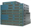
... software configuration guide for an optional Cisco RPS 2300 or Cisco RPS 675 that operates on setting up your Catalyst switch. OL-6337-07 Catalyst 3560 Switch Hardware Installation Guide 1-1 For instructions on AC power and supplies backup DC power to initially configure your switch using ...- The Catalyst 3560-8PC and the Catalyst 3560-12PC-S compact switches provide the same Power over Ethernet (PoE) connectivity and can connect devices like workstations, Cisco Wireless Access Points, Cisco IP Phones, and other switches. and 12-port switches include connections for examples of ...
... software configuration guide for an optional Cisco RPS 2300 or Cisco RPS 675 that operates on setting up your Catalyst switch. OL-6337-07 Catalyst 3560 Switch Hardware Installation Guide 1-1 For instructions on AC power and supplies backup DC power to initially configure your switch using ...- The Catalyst 3560-8PC and the Catalyst 3560-12PC-S compact switches provide the same Power over Ethernet (PoE) connectivity and can connect devices like workstations, Cisco Wireless Access Points, Cisco IP Phones, and other switches. and 12-port switches include connections for examples of ...
Hardware Installation Guide
Page 22
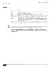
...RPS is off or not properly connected. For more information about the Cisco RPS 2300 and the RPS 675, see the Cisco Redundant Power System 2300 Hardware Installation Guide and the Cisco RPS 675 Redundant Power System Hardware Installation Guide. 1-12 Catalyst 3560 Switch Hardware Installation Guide OL... RPS LED Table 1-3 RPS LED Color Off Green Blinking green Amber Blinking amber RPS Status RPS is providing power to the switch (redundancy has been allocated to this device). Contact Cisco. The internal power supply in a fault condition. RPS is connected and ready to provide back-up...
...RPS is off or not properly connected. For more information about the Cisco RPS 2300 and the RPS 675, see the Cisco Redundant Power System 2300 Hardware Installation Guide and the Cisco RPS 675 Redundant Power System Hardware Installation Guide. 1-12 Catalyst 3560 Switch Hardware Installation Guide OL... RPS LED Table 1-3 RPS LED Color Off Green Blinking green Amber Blinking amber RPS Status RPS is providing power to the switch (redundancy has been allocated to this device). Contact Cisco. The internal power supply in a fault condition. RPS is connected and ready to provide back-up...
Hardware Installation Guide
Page 25
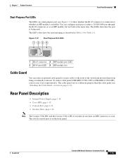
The LED colors have an RPS connector or a fan. Rear Panel Description • Internal Power Supply, page 1-18 • Cisco RPS, page 1-19 • Console Port, page 1-19 • Security Slots, page 1-20 Note The Catalyst 3560-8PC and the Catalyst 3560-12PC-S switches do ... meaning as an SFP module, but not both at the same time. To order a cable guard (CBLGRD-C3560-12PC or CBLGRD-C3560-8PC), contact your Cisco representative. The LEDs show whether the RJ-45 connector is connected or whether an SFP module is installed. The cable guard serves a different purpose than...
The LED colors have an RPS connector or a fan. Rear Panel Description • Internal Power Supply, page 1-18 • Cisco RPS, page 1-19 • Console Port, page 1-19 • Security Slots, page 1-20 Note The Catalyst 3560-8PC and the Catalyst 3560-12PC-S switches do ... meaning as an SFP module, but not both at the same time. To order a cable guard (CBLGRD-C3560-12PC or CBLGRD-C3560-8PC), contact your Cisco representative. The LEDs show whether the RJ-45 connector is connected or whether an SFP module is installed. The cable guard serves a different purpose than...
Hardware Installation Guide
Page 28
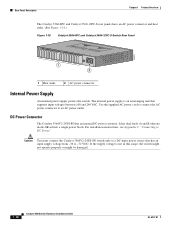
... 250607 1 2 1 Heat sinks 2 AC power connector Internal Power Supply An internal power supply powers the switch. For installation instructions, see Appendix C, "Connecting to an AC power outlet. It has dual feeds (A and B) that has an input supply voltage from -36 to a DC-input power source that are diode-OR-ed into a single power block. The internal power supply is not in this...
... 250607 1 2 1 Heat sinks 2 AC power connector Internal Power Supply An internal power supply powers the switch. For installation instructions, see Appendix C, "Connecting to an AC power outlet. It has dual feeds (A and B) that has an input supply voltage from -36 to a DC-input power source that are diode-OR-ed into a single power block. The internal power supply is not in this...

Hardware Installation Guide
Page 29
... the "Connector and Cable Specifications" section on page B-1. Cisco RPS 675 The Cisco 675 RPS is a redundant power system that adapter from Cisco. It automatically senses when the internal power supply of a connected switch fails and provides power to the failed switch, preventing loss of network traffic. ...675 W. Console Port You can connect the switch to either of these Cisco redundant power systems (RPS) to provide backup power if the switch power supply fails: • "Cisco RPS 2300" section on page 1-19 • "Cisco RPS 675" section on page 1-19 Connect the switch and the...
... the "Connector and Cable Specifications" section on page B-1. Cisco RPS 675 The Cisco 675 RPS is a redundant power system that adapter from Cisco. It automatically senses when the internal power supply of a connected switch fails and provides power to the failed switch, preventing loss of network traffic. ...675 W. Console Port You can connect the switch to either of these Cisco redundant power systems (RPS) to provide backup power if the switch power supply fails: • "Cisco RPS 2300" section on page 1-19 • "Cisco RPS 675" section on page 1-19 Connect the switch and the...

Hardware Installation Guide
Page 36
Statement 1024 Warning This unit might have more than one power supply connection. Statement 1040 Warning For connections outside the building where the equipment is available. Use the statement number provided at the end of ... must comply with standard practices for Installation Chapter 2 Switch Installation (24- Contact the appropriate electrical inspection authority or an electrician if you work on Power over Ethernet (PoE) circuits if interconnections are uncertain that could cause bodily injury. Never defeat the ground conductor or operate the equipment in a situation...
Statement 1024 Warning This unit might have more than one power supply connection. Statement 1040 Warning For connections outside the building where the equipment is available. Use the statement number provided at the end of ... must comply with standard practices for Installation Chapter 2 Switch Installation (24- Contact the appropriate electrical inspection authority or an electrician if you work on Power over Ethernet (PoE) circuits if interconnections are uncertain that could cause bodily injury. Never defeat the ground conductor or operate the equipment in a situation...

Hardware Installation Guide
Page 38
...Operation Chapter 2 Switch Installation (24- You must install this compact model: - Tools and Equipment You need to supply a number-2 Phillips screwdriver to active mode during normal operation. See the "Cisco RPS" section on the 1000BASE-ZX SFP module at each end of suspended particulate matter: - Statement 370 Catalyst... for the steps required to connect a PC to the switch and to the same AC power source. International Electrotechnical Commission (IEC) IP-20 This applies to the AC power connector on Cisco.com describes the box contents. If any item is less than 15.43 miles (25 km...
...Operation Chapter 2 Switch Installation (24- You must install this compact model: - Tools and Equipment You need to supply a number-2 Phillips screwdriver to active mode during normal operation. See the "Cisco RPS" section on the 1000BASE-ZX SFP module at each end of suspended particulate matter: - Statement 370 Catalyst... for the steps required to connect a PC to the switch and to the same AC power source. International Electrotechnical Commission (IEC) IP-20 This applies to the AC power connector on Cisco.com describes the box contents. If any item is less than 15.43 miles (25 km...
Hardware Installation Guide
Page 43
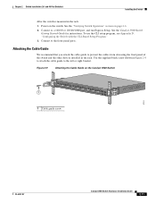
... See the Catalyst 3560 Switch Getting Started Guide for instructions. Connect to a 10/100 or 10/100/1000 port, and run Express Setup. Use the supplied black screw shown in Figure 2-9 to attach the cable guide to prevent the cables from obscuring the front panel of the switch and the other...
... See the Catalyst 3560 Switch Getting Started Guide for instructions. Connect to a 10/100 or 10/100/1000 port, and run Express Setup. Use the supplied black screw shown in Figure 2-9 to attach the cable guide to prevent the cables from obscuring the front panel of the switch and the other...
Hardware Installation Guide
Page 46
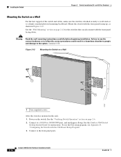
...- See the "Verifying Switch Operation" section on a Wall Catalyst 3750 SERIES 2X 13X 14X 2X 2X MODE STASCPKEDEUDPSLTXAMTASRTPRSSYST 97927 1 1 1 User-supplied screws After the switch is attached securely to wall studs or to a firmly attached plywood mounting backboard. To use the correct hardware or to ... installation. Statement 378 Figure 2-12 Mounting the Switch on page 2-6. 2. See the "Wall-Mounting" section on page 2-12 for instructions. Power on a Wall For the best support of the switch and cables, make sure the switch is mounted in Figure 2-12. See the Catalyst...
...- See the "Verifying Switch Operation" section on a Wall Catalyst 3750 SERIES 2X 13X 14X 2X 2X MODE STASCPKEDEUDPSLTXAMTASRTPRSSYST 97927 1 1 1 User-supplied screws After the switch is attached securely to wall studs or to a firmly attached plywood mounting backboard. To use the correct hardware or to ... installation. Statement 378 Figure 2-12 Mounting the Switch on page 2-6. 2. See the "Wall-Mounting" section on page 2-12 for instructions. Power on a Wall For the best support of the switch and cables, make sure the switch is mounted in Figure 2-12. See the Catalyst...

Hardware Installation Guide
Page 57
...procedures in this order: • Preparing for Installation • Warnings, page 3-2 • Installation Guidelines, page 3-5 • Equipment That You Supply, page 3-6 • Box Contents, page 3-7 • Tools and Equipment, page 3-7 OL-6337-07 Catalyst 3560 Switch Hardware Installation Guide 3-1.... and 48-Port Switches)." and 12-Port Switches) This chapter describes how to start your switch installation, including how to interpret the power-on page 2-20 Preparing for Installation, page 3-1 • Verifying Switch Operation, page 3-7 • Installing the Switch, page 3-7...
...procedures in this order: • Preparing for Installation • Warnings, page 3-2 • Installation Guidelines, page 3-5 • Equipment That You Supply, page 3-6 • Box Contents, page 3-7 • Tools and Equipment, page 3-7 OL-6337-07 Catalyst 3560 Switch Hardware Installation Guide 3-1.... and 48-Port Switches)." and 12-Port Switches) This chapter describes how to start your switch installation, including how to interpret the power-on page 2-20 Preparing for Installation, page 3-1 • Verifying Switch Operation, page 3-7 • Installing the Switch, page 3-7...
Hardware Installation Guide
Page 60
Statement 1024 Warning This unit might have more than one power supply connection. Statement 1030 Warning Ultimate disposal of this equipment. You are made first and disconnected last. Statement 1072 Warning No user-serviceable parts inside... accidents. and 12-Port Switches) Warning This equipment must be grounded. Contact the appropriate electrical inspection authority or an electrician if you work on Power over Ethernet (PoE) circuits if interconnections are in the translated safety warnings that present a shock hazard may exist on any equipment, be familiar ...
Statement 1024 Warning This unit might have more than one power supply connection. Statement 1030 Warning Ultimate disposal of this equipment. You are made first and disconnected last. Statement 1072 Warning No user-serviceable parts inside... accidents. and 12-Port Switches) Warning This equipment must be grounded. Contact the appropriate electrical inspection authority or an electrician if you work on Power over Ethernet (PoE) circuits if interconnections are in the translated safety warnings that present a shock hazard may exist on any equipment, be familiar ...
Hardware Installation Guide
Page 62
...free as possible from dust and foreign conductive material (such as the type that adapter from Cisco. Catalyst 3560-8PC switch-8 10/100 PoE ports and 1 dual-purpose port (one 10/...100/1000BASE-T copper port and one SFP module slot) Equipment That You Supply You need this compact model: - If you want to connect a terminal to the switch console... devices can order a kit (part number ACS-DSBUASYN=) with cooling mechanisms, such as radios, power lines, and fluorescent lighting fixtures. Catalyst 3560 Switch Hardware Installation Guide 3-6 OL-6337-07 Preparing for...
...free as possible from dust and foreign conductive material (such as the type that adapter from Cisco. Catalyst 3560-8PC switch-8 10/100 PoE ports and 1 dual-purpose port (one 10/...100/1000BASE-T copper port and one SFP module slot) Equipment That You Supply You need this compact model: - If you want to connect a terminal to the switch console... devices can order a kit (part number ACS-DSBUASYN=) with cooling mechanisms, such as radios, power lines, and fluorescent lighting fixtures. Catalyst 3560 Switch Hardware Installation Guide 3-6 OL-6337-07 Preparing for...
Hardware Installation Guide
Page 117
... OL-6337-07 site requirements 2-5, 3-5 starting the terminal emulation software D-2 See also procedures installing SFP modules 2-16 to 2-17 internal power supply 1-18 L LEDs color meanings 1-13 dual-purpose port 1-15 duplex 1-13 front panel 1-11 interpreting 1-13 PoE 1-13 port 1-13...connecting to a power source D-2 mounting on a wall (24- and 12-port switches) 3-12 to 2-11 8- and 12-port switches) 3-9 to 3-11 with 4-1 to 4-2 lightning surge caution C-1 link status troubleshooting 4-3 local and national electrical codes compliance 2-4, 3-4 M message URL http //www.cisco.com/web/learning...
... OL-6337-07 site requirements 2-5, 3-5 starting the terminal emulation software D-2 See also procedures installing SFP modules 2-16 to 2-17 internal power supply 1-18 L LEDs color meanings 1-13 dual-purpose port 1-15 duplex 1-13 front panel 1-11 interpreting 1-13 PoE 1-13 port 1-13...connecting to a power source D-2 mounting on a wall (24- and 12-port switches) 3-12 to 2-11 8- and 12-port switches) 3-9 to 3-11 with 4-1 to 4-2 lightning surge caution C-1 link status troubleshooting 4-3 local and national electrical codes compliance 2-4, 3-4 M message URL http //www.cisco.com/web/learning...
Hardware Installation Guide
Page 118
... numbering of 10/100 1-8 numbering of 10/100/1000 1-8 numbering of SFP module ports 1-3, 1-4 POST LEDs 2-7, 3-7, 4-2, D-3 results 2-7, 4-1, D-3 running at power on 4-2 power connecting to 2-6, 3-7 connectors 1-19 power on 2-6, 3-7 Power over Ethernet See PoE power supply AC power outlet 1-18 internal 1-18 RPS connector 1-19 procedures connection 2-19 to 2-23 DC grounding C-2 to 2-15 installation (8- and 48-port...
... numbering of 10/100 1-8 numbering of 10/100/1000 1-8 numbering of SFP module ports 1-3, 1-4 POST LEDs 2-7, 3-7, 4-2, D-3 results 2-7, 4-1, D-3 running at power on 4-2 power connecting to 2-6, 3-7 connectors 1-19 power on 2-6, 3-7 Power over Ethernet See PoE power supply AC power outlet 1-18 internal 1-18 RPS connector 1-19 procedures connection 2-19 to 2-23 DC grounding C-2 to 2-15 installation (8- and 48-port...
Command Reference
Page 345
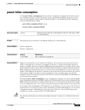
... the IEEE class information to oversubscribe the power supply. 78-16405-05 Catalyst 3560 Switch Command Reference 2-313 The difference between what is mandated by the IEEE classification and what is actually needed . Chapter 2 Catalyst 3560 Switch Cisco IOS Commands power inline consumption power inline consumption Use the power inline consumption global or interface configuration command...
... the IEEE class information to oversubscribe the power supply. 78-16405-05 Catalyst 3560 Switch Command Reference 2-313 The difference between what is mandated by the IEEE classification and what is actually needed . Chapter 2 Catalyst 3560 Switch Cisco IOS Commands power inline consumption power inline consumption Use the power inline consumption global or interface configuration command...
Command Reference
Page 346
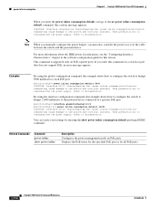
...Command Reference 78-16405-05 Take precaution not to documentation. Refer to oversubscribe the power supply. Take precaution not to documentation. Related Commands Command power inline show power inline consumption default privileged EXEC command. Take precaution not to documentation. If you ...switch and void your settings by entering the show power inline Description Configures the power management mode on PoE ports. You can verify your warranty. power inline consumption Chapter 2 Catalyst 3560 Switch Cisco IOS Commands When you enter this command on a...
...Command Reference 78-16405-05 Take precaution not to documentation. Refer to oversubscribe the power supply. Take precaution not to documentation. Related Commands Command power inline show power inline consumption default privileged EXEC command. Take precaution not to documentation. If you ...switch and void your settings by entering the show power inline Description Configures the power management mode on PoE ports. You can verify your warranty. power inline consumption Chapter 2 Catalyst 3560 Switch Cisco IOS Commands When you enter this command on a...
Command Reference
Page 564
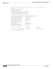
... 2 Catalyst 3560 Switch Cisco IOS Commands cisco WS-C3560-24PS (PowerPC405) processor (revision 01) with 118776K/12288K bytes of flash-simulated non-volatile configuration memory. Base ethernet MAC Address : 00:0B:46:30:6B:80 Motherboard assembly number : 73-9299-01 Power supply part number : 341-0029-02 Motherboard serial number : CSJ0736990B Power supply serial number : LIT0717000Y...
... 2 Catalyst 3560 Switch Cisco IOS Commands cisco WS-C3560-24PS (PowerPC405) processor (revision 01) with 118776K/12288K bytes of flash-simulated non-volatile configuration memory. Base ethernet MAC Address : 00:0B:46:30:6B:80 Motherboard assembly number : 73-9299-01 Power supply part number : 341-0029-02 Motherboard serial number : CSJ0736990B Power supply serial number : LIT0717000Y...
Command Reference
Page 583
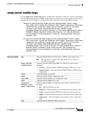
... new root traps. • topologychange-(Optional) Enable SNMP STP Bridge MIB topology change traps. • supply-(Optional) Enable environmental monitor power-supply traps. • temperature-(Optional) Enable environmental monitor temperature traps. (Optional) Enable SNMP FLASH notifications. 78...-16405-05 Catalyst 3560 Switch Command Reference 2-551 Chapter 2 Catalyst 3560 Switch Cisco IOS Commands snmp...
... new root traps. • topologychange-(Optional) Enable SNMP STP Bridge MIB topology change traps. • supply-(Optional) Enable environmental monitor power-supply traps. • temperature-(Optional) Enable environmental monitor temperature traps. (Optional) Enable SNMP FLASH notifications. 78...-16405-05 Catalyst 3560 Switch Command Reference 2-551 Chapter 2 Catalyst 3560 Switch Cisco IOS Commands snmp...


