
Hardware Installation Guide
Page 3
...100 Ports 1-11 10/100/1000 Ports 1-11 PoE Ports (Only Catalyst 2960 PoE Switches) 1-12 SFP Module Slots 1-13 Dual-Purpose Port 1-13 Power Input Port (Catalyst 2960PD-8TT-L Switch) 1-13 LEDs 1-14 System LED 1-15 RPS LED 1-16 Port LEDs and Modes 1-16 Dual-Purpose Port ...LEDs 1-18 Cable Guard for the Catalyst 2960 8-Port Switches 1-19 Rear Panel Description 1-19 Internal Power Supply 1-20 Cisco RPS 1-20 Cisco RPS 2300 1-20 Cisco RPS 675 1-21 Console Port 1-21 Security Slots 1-21 Management Options 1-22 Network Configurations 1-22 Catalyst 2960 Switch Hardware Installation...
...100 Ports 1-11 10/100/1000 Ports 1-11 PoE Ports (Only Catalyst 2960 PoE Switches) 1-12 SFP Module Slots 1-13 Dual-Purpose Port 1-13 Power Input Port (Catalyst 2960PD-8TT-L Switch) 1-13 LEDs 1-14 System LED 1-15 RPS LED 1-16 Port LEDs and Modes 1-16 Dual-Purpose Port ...LEDs 1-18 Cable Guard for the Catalyst 2960 8-Port Switches 1-19 Rear Panel Description 1-19 Internal Power Supply 1-20 Cisco RPS 1-20 Cisco RPS 2300 1-20 Cisco RPS 675 1-21 Console Port 1-21 Security Slots 1-21 Management Options 1-22 Network Configurations 1-22 Catalyst 2960 Switch Hardware Installation...

Hardware Installation Guide
Page 6
... C-1 Accessing the CLI Through Express Setup C-1 Accessing the CLI Through the Console Port C-2 Connecting to the Console Port C-3 Starting the Terminal Emulation Software C-3 Connecting to a Power Source C-4 Entering the Initial Configuration Information C-4 IP Settings C-5 Completing the Setup Program C-5 Catalyst 2960 Switch Hardware Installation Guide vi OL-7075-09
... C-1 Accessing the CLI Through Express Setup C-1 Accessing the CLI Through the Console Port C-2 Connecting to the Console Port C-3 Starting the Terminal Emulation Software C-3 Connecting to a Power Source C-4 Entering the Initial Configuration Information C-4 IP Settings C-5 Completing the Setup Program C-5 Catalyst 2960 Switch Hardware Installation Guide vi OL-7075-09
Hardware Installation Guide
Page 9
... and set content to be delivered directly to your desktop using a reader application. OL-7075-09 Catalyst 2960 Switch Hardware Installation Guide ix Preface • Cisco Redundant Power System 2300 Hardware Installation Guide • Cisco RPS 675 Redundant Power System Hardware Installation Guide These compatibility matrix documents are a free service and...
... and set content to be delivered directly to your desktop using a reader application. OL-7075-09 Catalyst 2960 Switch Hardware Installation Guide ix Preface • Cisco Redundant Power System 2300 Hardware Installation Guide • Cisco RPS 675 Redundant Power System Hardware Installation Guide These compatibility matrix documents are a free service and...

Hardware Installation Guide
Page 12
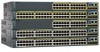
...) LAN-Base 8 10/100BASE-TX Ethernet ports and 1 10/100/1000 port that receives power (no fan, RPS port, or SFP module slot) LAN-Base 24 10/100BASE-TX ports, 8 of which are Power over Ethernet (PoE), and 2 10/100/1000 ports (no SFP module slot) LAN-Base...section on page 1-9 for these switch models. See Chapter 3, "Switch Installation (8-Port Switches)," for the installation instructions for more information. They can be mounted with Cisco prestandard PoE and IEEE 802.3af: • Catalyst 2960-24LC-S • Catalyst 2960-24LT-L • Catalyst 2960-24PC-L • Catalyst 2960-24PC-S &#...
...) LAN-Base 8 10/100BASE-TX Ethernet ports and 1 10/100/1000 port that receives power (no fan, RPS port, or SFP module slot) LAN-Base 24 10/100BASE-TX ports, 8 of which are Power over Ethernet (PoE), and 2 10/100/1000 ports (no SFP module slot) LAN-Base...section on page 1-9 for these switch models. See Chapter 3, "Switch Installation (8-Port Switches)," for the installation instructions for more information. They can be mounted with Cisco prestandard PoE and IEEE 802.3af: • Catalyst 2960-24LC-S • Catalyst 2960-24LT-L • Catalyst 2960-24PC-L • Catalyst 2960-24PC-S &#...

Hardware Installation Guide
Page 13
... information about switch support for an optional Cisco RPS 2300 or Cisco RPS 675 redundant power system that operates on specific switches, see the Cisco Gigabit Ethernet Transceiver Modules Compatibility Matrix at this Cisco.com URL: http://www.cisco.com/en/US/docs/interfaces_modules/transceiver_modules/compatibility/...48TC-L switches support all the SFP modules. The Catalyst 2960-8TC-L, 2960G-8TC-L, and 2960-8TC-S switches do not have a redundant power system (RPS) connector for the RPS models. Some Catalyst 2960 switches have an RPS connector: • Catalyst 2960-8TC-L • ...
... information about switch support for an optional Cisco RPS 2300 or Cisco RPS 675 redundant power system that operates on specific switches, see the Cisco Gigabit Ethernet Transceiver Modules Compatibility Matrix at this Cisco.com URL: http://www.cisco.com/en/US/docs/interfaces_modules/transceiver_modules/compatibility/...48TC-L switches support all the SFP modules. The Catalyst 2960-8TC-L, 2960G-8TC-L, and 2960-8TC-S switches do not have a redundant power system (RPS) connector for the RPS models. Some Catalyst 2960 switches have an RPS connector: • Catalyst 2960-8TC-L • ...

Hardware Installation Guide
Page 14
..., page 1-11 • PoE Ports (Only Catalyst 2960 PoE Switches), page 1-12 • SFP Module Slots, page 1-13 • Dual-Purpose Port, page 1-13 • Power Input Port (Catalyst 2960PD-8TT-L Switch), page 1-13 • LEDs, page 1-14 • Cable Guard for that is above port 4, and so on. These switches...
..., page 1-11 • PoE Ports (Only Catalyst 2960 PoE Switches), page 1-12 • SFP Module Slots, page 1-13 • Dual-Purpose Port, page 1-13 • Power Input Port (Catalyst 2960PD-8TT-L Switch), page 1-13 • LEDs, page 1-14 • Cable Guard for that is above port 4, and so on. These switches...

Hardware Installation Guide
Page 16
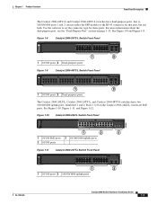
... 1 2 1X 3 4 5 6 7 8 9 10 11 12 13 14 15 16 17 18 19 20 21 22 23 24 11X 13X 23X Catalyst 2960 Series PoE-24 2X POWER OVER ETHERNET 12X 14X 1 2 24X 204641 1 2 1 10/100 PoE ports 2 Dual-purpose ports Figure 1-6 Catalyst 2960-24PC-S Switch Front Panel 206731 1 2 1 10/100 PoE ports...
... 1 2 1X 3 4 5 6 7 8 9 10 11 12 13 14 15 16 17 18 19 20 21 22 23 24 11X 13X 23X Catalyst 2960 Series PoE-24 2X POWER OVER ETHERNET 12X 14X 1 2 24X 204641 1 2 1 10/100 PoE ports 2 Dual-purpose ports Figure 1-6 Catalyst 2960-24PC-S Switch Front Panel 206731 1 2 1 10/100 PoE ports...
Hardware Installation Guide
Page 17
... 1 2 1X 34 5 6 7 8 9 10 11 12 13 14 15 16 17 18 19 20 21 22 23 24 Catalyst 2960 Series PoE-8 11X 13X 23X 2X POWER OVER ETHERNET 12X 14X 1 2 24X 1 2 3 1 10/100 PoE ports 3 10/100/1000 uplink ports 2 10/100 ports Figure 1-11 Catalyst 2960-24TT-L Switch Front Panel...
... 1 2 1X 34 5 6 7 8 9 10 11 12 13 14 15 16 17 18 19 20 21 22 23 24 Catalyst 2960 Series PoE-8 11X 13X 23X 2X POWER OVER ETHERNET 12X 14X 1 2 24X 1 2 3 1 10/100 PoE ports 3 10/100/1000 uplink ports 2 10/100 ports Figure 1-11 Catalyst 2960-24TT-L Switch Front Panel...

Hardware Installation Guide
Page 18
... not both. Use the software to 48 on . Figure 1-13 Catalyst 2960-48PST-L Switch Front Panel 3 1 2 3 4 5 6 SYST 1X RPS STAT DUPLX SPEED PoE MODE 2X POWER OVER ETHERNET 7 8 9 10 11 12 13 14 15 16 17 18 19 20 21 22 23 24 25 26 27 28 29 30 31 32...
... not both. Use the software to 48 on . Figure 1-13 Catalyst 2960-48PST-L Switch Front Panel 3 1 2 3 4 5 6 SYST 1X RPS STAT DUPLX SPEED PoE MODE 2X POWER OVER ETHERNET 7 8 9 10 11 12 13 14 15 16 17 18 19 20 21 22 23 24 25 26 27 28 29 30 31 32...

Hardware Installation Guide
Page 19
... panel has a console port, eight 10/100 ports, and a 10/100/1000 uplink port that can also receive power from an upstream PoE switch. The switch can receive power from an optional AC power adapter that is connected through the rear panel. 204643 Figure 1-17 Catalyst 2960PD-8TT-L Switch Front Panel SYST STAT... DPLX SPD 1x 2x 3x 4x 5x 6x 7x 8x CONSOLE MODE Catalyst 2960 Series 1 PoE INPUT 1 2 3 1 Console port 3 10/100/1000 power input port 2 10/100 ports OL-7075-09 Catalyst 2960 Switch Hardware Installation Guide 1-9
... panel has a console port, eight 10/100 ports, and a 10/100/1000 uplink port that can also receive power from an upstream PoE switch. The switch can receive power from an optional AC power adapter that is connected through the rear panel. 204643 Figure 1-17 Catalyst 2960PD-8TT-L Switch Front Panel SYST STAT... DPLX SPD 1x 2x 3x 4x 5x 6x 7x 8x CONSOLE MODE Catalyst 2960 Series 1 PoE INPUT 1 2 3 1 Console port 3 10/100/1000 power input port 2 10/100 ports OL-7075-09 Catalyst 2960 Switch Hardware Installation Guide 1-9

Hardware Installation Guide
Page 22
... within the restricted access location are made using uninsulated exposed metal contacts, conductors, or terminals. The Cisco prestandard PoE is connected. Many legacy powered devices, including older Cisco IP phones and access points that do not fully support IEEE 802.3af, might not support PoE...ports on the Catalyst 2960 switches deliver up to the AC power source as an IEEE 802.3af-compliant powered device, a Cisco prestandard IP phone, or a Cisco prestandard Cisco access point, is also supported for Cisco IP Phones and Cisco Aironet Access Points. • Each of the PoE ports ...
... within the restricted access location are made using uninsulated exposed metal contacts, conductors, or terminals. The Cisco prestandard PoE is connected. Many legacy powered devices, including older Cisco IP phones and access points that do not fully support IEEE 802.3af, might not support PoE...ports on the Catalyst 2960 switches deliver up to the AC power source as an IEEE 802.3af-compliant powered device, a Cisco prestandard IP phone, or a Cisco prestandard Cisco access point, is also supported for Cisco IP Phones and Cisco Aironet Access Points. • Each of the PoE ports ...

Hardware Installation Guide
Page 23
... Ethernet switch that first links up. You use Gigabit Ethernet SFP modules for Gigabit uplink connections and 100-Megabit SFP modules for your Cisco representative. (See Figure 1-22.) OL-7075-09 Catalyst 2960 Switch Hardware Installation Guide 1-13 The switch activates only one shows the ...status of the SFP module port. By default, the switch dynamically selects the interface type that provides power (complies with dual front ends-an RJ-45 connector and an SFP module connector. For more information about cabling requirements, see the ...
... Ethernet switch that first links up. You use Gigabit Ethernet SFP modules for Gigabit uplink connections and 100-Megabit SFP modules for your Cisco representative. (See Figure 1-22.) OL-7075-09 Catalyst 2960 Switch Hardware Installation Guide 1-13 The switch activates only one shows the ...status of the SFP module port. By default, the switch dynamically selects the interface type that provides power (complies with dual front ends-an RJ-45 connector and an SFP module connector. For more information about cabling requirements, see the ...

Hardware Installation Guide
Page 24
... 1x 2x 3x 4x 5x 6x 7x 8x CONSOLE MODE Catalyst 2960 Series 1 PoE INPUT 1 204644 Figure 1-22 1 Connecting Through an External AC Power Adapter 48V , 0.3 A 270433 LEDs 1 Power adapter port You can use the switch LEDs to monitor individual switches and switch clusters. The four Catalyst 2960 8-port switches and these...
... 1x 2x 3x 4x 5x 6x 7x 8x CONSOLE MODE Catalyst 2960 Series 1 PoE INPUT 1 204644 Figure 1-22 1 Connecting Through an External AC Power Adapter 48V , 0.3 A 270433 LEDs 1 Power adapter port You can use the switch LEDs to monitor individual switches and switch clusters. The four Catalyst 2960 8-port switches and these...

Hardware Installation Guide
Page 25
...only on . The System LED shows whether the system is receiving power and is not functioning properly. Table 1-2 System LED Color Off Green Amber System Status System is operating normally. System is receiving power but is functioning properly. OL-7075-09 Catalyst 2960 Switch Hardware... Installation Guide 1-15 System is not powered on the Catalyst 2960 PoE switches. Table 1-2 lists the LED colors and their ...
...only on . The System LED shows whether the system is receiving power and is not functioning properly. Table 1-2 System LED Color Off Green Amber System Status System is operating normally. System is receiving power but is functioning properly. OL-7075-09 Catalyst 2960 Switch Hardware... Installation Guide 1-15 System is not powered on the Catalyst 2960 PoE switches. Table 1-2 lists the LED colors and their ...

Hardware Installation Guide
Page 26
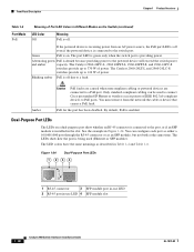
... mode or at 10 or 100 Mb/s in a fault condition. Contact Cisco Systems. The internal power supply in a switch has failed, and the RPS is providing power to the switch (redundancy has been allocated to provide back-up power, if required. Note The Catalyst 2960 8-port switches, and the Catalyst ... green. Port LEDs and Modes The port LEDs, as a group or individually, display information about the switch and about the Cisco RPS 2300 or the Cisco RPS 675, see the related hardware installation guide for Port LEDs Selected Mode LED Port Mode Description STAT Port status The port...
... mode or at 10 or 100 Mb/s in a fault condition. Contact Cisco Systems. The internal power supply in a switch has failed, and the RPS is providing power to the switch (redundancy has been allocated to provide back-up power, if required. Note The Catalyst 2960 8-port switches, and the Catalyst ... green. Port LEDs and Modes The port LEDs, as a group or individually, display information about the switch and about the Cisco RPS 2300 or the Cisco RPS 675, see the related hardware installation guide for Port LEDs Selected Mode LED Port Mode Description STAT Port status The port...

Hardware Installation Guide
Page 27
None of the 10/100 PoE ports have been denied power or are monitored for possible loops. PoE mode is selected, and the PoE status is highlighted. Table 1-6 Meaning of the ports has a PoE fault. Blinking ... are in full-duplex mode or at 100 Mb/s. When you change port modes, the meanings of the 10/100 PoE ports has been denied power, or at 100 Mb/s. Port is not selected. PoE mode is sending or receiving data. Link present. Alternating green-amber Link fault. Blinking green Activity...
None of the 10/100 PoE ports have been denied power or are monitored for possible loops. PoE mode is selected, and the PoE status is highlighted. Table 1-6 Meaning of the ports has a PoE fault. Blinking ... are in full-duplex mode or at 100 Mb/s. When you change port modes, the meanings of the 10/100 PoE ports has been denied power, or at 100 Mb/s. Port is not selected. PoE mode is sending or receiving data. Link present. Alternating green-amber Link fault. Blinking green Activity...
Hardware Installation Guide
Page 28
... port LED is green only when the switch port is denied because providing power to the powered device will exceed the switch power and amber capacity. Alternating green PoE is providing power. By default, PoE is being used to connect Cisco prestandard IP Phones or wireless access points or IEEE 802.3af-compliant devices... to PoE ports. The LEDs show whether an RJ-45 connector is connected to the port, or if an SFP module is off due to a fault. You must remove from an AC power source, the...
... port LED is green only when the switch port is denied because providing power to the powered device will exceed the switch power and amber capacity. Alternating green PoE is providing power. By default, PoE is being used to connect Cisco prestandard IP Phones or wireless access points or IEEE 802.3af-compliant devices... to PoE ports. The LEDs show whether an RJ-45 connector is connected to the port, or if an SFP module is off due to a fault. You must remove from an AC power source, the...
Hardware Installation Guide
Page 29
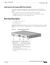
... being accidentally removed. OL-7075-09 Catalyst 2960 Switch Hardware Installation Guide 1-19 The Catalyst 2960 8-port switches have an AC internal power supply. To order a cable guard, contact your Cisco representative using these part numbers: • CBLGRD-C2960-8TC: Catalyst 2960-8TC-L, 2960-8TC-S, and 2960PD-8TT-L switches • CBLGRD-C2960G-8TC...
... being accidentally removed. OL-7075-09 Catalyst 2960 Switch Hardware Installation Guide 1-19 The Catalyst 2960 8-port switches have an AC internal power supply. To order a cable guard, contact your Cisco representative using these part numbers: • CBLGRD-C2960-8TC: Catalyst 2960-8TC-L, 2960-8TC-S, and 2960PD-8TT-L switches • CBLGRD-C2960G-8TC...
Hardware Installation Guide
Page 30
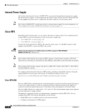
...-L Switch)" section on the installed power-supply modules. Use the supplied AC power cord to connect the AC power connector to either of network traffic. Cisco RPS Depending on the switch model, you can configure these Cisco redundant power systems (RPS) to provide backup power if the switch power supply fails: • "Cisco RPS 2300" section on page 1-20...
...-L Switch)" section on the installed power-supply modules. Use the supplied AC power cord to connect the AC power connector to either of network traffic. Cisco RPS Depending on the switch model, you can configure these Cisco redundant power systems (RPS) to provide backup power if the switch power supply fails: • "Cisco RPS 2300" section on page 1-20...

Hardware Installation Guide
Page 31
... to a PC by the RPS • Obtain status reports for the RPS power-supply module • Read and monitor backup, failure, and exception history Cisco RPS 675 The Cisco 675 RPS is a redundant power system that supports six network devices and provides power to secure either or both sides of the switch. Security Slots The...
... to a PC by the RPS • Obtain status reports for the RPS power-supply module • Read and monitor backup, failure, and exception history Cisco RPS 675 The Cisco 675 RPS is a redundant power system that supports six network devices and provides power to secure either or both sides of the switch. Security Slots The...


