
Hardware Installation Guide
Page 2
...) Any Internet Protocol (IP) addresses used in the United States and certain other countries. Changing the Way We Work, Live, Play, and Learn, Cisco Capital, Cisco Capital (Design), Cisco:Financed (Stylized), Cisco Store, Flip Gift Card, and One Million Acts of California. USERS MUST TAKE FULL RESPONSIBILITY FOR THEIR APPLICATION OF ANY PRODUCTS. The following information is not installed in this manual generates and...
...) Any Internet Protocol (IP) addresses used in the United States and certain other countries. Changing the Way We Work, Live, Play, and Learn, Cisco Capital, Cisco Capital (Design), Cisco:Financed (Stylized), Cisco Store, Flip Gift Card, and One Million Acts of California. USERS MUST TAKE FULL RESPONSIBILITY FOR THEIR APPLICATION OF ANY PRODUCTS. The following information is not installed in this manual generates and...

Hardware Installation Guide
Page 21
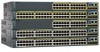
... switch software configuration guide or the switch command reference. 10/100/1000 Ports You can use a crossover cable. When you connect the switch to workstations, servers, routers, and Cisco IP Phones, be within 328 feet (100 meters). 100BASE-TX traffic requires a Category 5 or higher cable. 10BASE-T traffic can also set the port for the cables are described in the CLI to switches or hubs, use the mdix auto interface configuration command in Appendix B, "Connector and Cable Specifications." Chapter 1 Product Overview Front Panel...
... switch software configuration guide or the switch command reference. 10/100/1000 Ports You can use a crossover cable. When you connect the switch to workstations, servers, routers, and Cisco IP Phones, be within 328 feet (100 meters). 100BASE-TX traffic requires a Category 5 or higher cable. 10BASE-T traffic can also set the port for the cables are described in the CLI to switches or hubs, use the mdix auto interface configuration command in Appendix B, "Connector and Cable Specifications." Chapter 1 Product Overview Front Panel...

Hardware Installation Guide
Page 22
... powered device, a Cisco prestandard IP phone, or a Cisco prestandard Cisco access point, is the default. - The device manager, Network Assistant, and the CLI provide PoE settings for the powered device. The Auto setting is connected. In that came with the switch. Front Panel Description Chapter 1 Product Overview PoE Ports (Only Catalyst 2960 PoE Switches) This section applies only to the powered device. For information about Cisco IP Phones and Cisco Aironet Access Points, see the switch software configuration guide. Auto: When you can control whether or not a Catalyst 2960 PoE...
... powered device, a Cisco prestandard IP phone, or a Cisco prestandard Cisco access point, is the default. - The device manager, Network Assistant, and the CLI provide PoE settings for the powered device. The Auto setting is connected. In that came with the switch. Front Panel Description Chapter 1 Product Overview PoE Ports (Only Catalyst 2960 PoE Switches) This section applies only to the powered device. For information about Cisco IP Phones and Cisco Aironet Access Points, see the switch software configuration guide. Auto: When you can control whether or not a Catalyst 2960 PoE...

Hardware Installation Guide
Page 23
...a fiber-optic SFP module. Power Input Port (Catalyst 2960PD-8TT-L Switch) The Catalyst 2960PD-8TT-L can use fiber-optic cables with LC connectors to connect to a copper SFP module. Through a 10/100/1000 port from these SFP modules, see your switch software. Chapter 1 Product Overview Front Panel Description SFP Module Slots The Catalyst 2960 switches (other switches. For more information about cabling requirements, see the software configuration guide. By default, the switch dynamically selects the interface type that connects to other than those listed) use Category...
...a fiber-optic SFP module. Power Input Port (Catalyst 2960PD-8TT-L Switch) The Catalyst 2960PD-8TT-L can use fiber-optic cables with LC connectors to connect to a copper SFP module. Through a 10/100/1000 port from these SFP modules, see your switch software. Chapter 1 Product Overview Front Panel Description SFP Module Slots The Catalyst 2960 switches (other switches. For more information about cabling requirements, see the software configuration guide. By default, the switch dynamically selects the interface type that connects to other than those listed) use Category...
Hardware Installation Guide
Page 32
... the Catalyst 2960 Switch Command Reference on Cisco.com for an explanation of Cisco LAN switches, core switches, routers, access points, IP phones, and PIX firewalls. For more information, see the Getting Started with Cisco Network Assistant guide on Cisco.com for more information. • SNMP network management You can use the CLI, go /cna For information on starting Network Assistant, see the device manager online help. • Cisco IOS command-line interface (CLI) The switch CLI is based on the switch. For setup instructions that use to set configuration parameters and...
... the Catalyst 2960 Switch Command Reference on Cisco.com for an explanation of Cisco LAN switches, core switches, routers, access points, IP phones, and PIX firewalls. For more information, see the Getting Started with Cisco Network Assistant guide on Cisco.com for more information. • SNMP network management You can use the CLI, go /cna For information on starting Network Assistant, see the device manager online help. • Cisco IOS command-line interface (CLI) The switch CLI is based on the switch. For setup instructions that use to set configuration parameters and...
Hardware Installation Guide
Page 34
... is not connected to power lines, remove jewelry (including rings, necklaces, and watches). and 48-Port Switches) Warnings These warnings are translated into several languages in a central office environment. Statement 1004 Catalyst 2960 Switch Hardware Installation Guide 2-2 OL-7075-09 Statement 1001 Warning Read the installation instructions before beginning installation. Statement 43 Warning Do not stack the chassis on the system or connect or disconnect cables during...
... is not connected to power lines, remove jewelry (including rings, necklaces, and watches). and 48-Port Switches) Warnings These warnings are translated into several languages in a central office environment. Statement 1004 Catalyst 2960 Switch Hardware Installation Guide 2-2 OL-7075-09 Statement 1001 Warning Read the installation instructions before beginning installation. Statement 43 Warning Do not stack the chassis on the system or connect or disconnect cables during...

Hardware Installation Guide
Page 36
... Switch Hardware Installation Guide 2-4 OL-7075-09 A restricted access area can be sure to observe these fans and blowers can use of the hazard. For information applicable to the Catalyst 2960 8-port switches. However, these requirements: • For 10/100/1000 ports, cable lengths from construction activities). Statement 1072 Warning No user-serviceable parts inside the chassis, which lists the cable specifications for 1000BASE-X and 100BASE-X SFP modules for Particulate Matter Cisco Ethernet switches...
... Switch Hardware Installation Guide 2-4 OL-7075-09 A restricted access area can be sure to observe these fans and blowers can use of the hazard. For information applicable to the Catalyst 2960 8-port switches. However, these requirements: • For 10/100/1000 ports, cable lengths from construction activities). Statement 1072 Warning No user-serviceable parts inside the chassis, which lists the cable specifications for 1000BASE-X and 100BASE-X SFP modules for Particulate Matter Cisco Ethernet switches...

Hardware Installation Guide
Page 38
... your specific switch; and 48-port switches. Warning To prevent bodily injury when mounting or servicing this unit in a rack, you must take special precautions to all 24- If a switch fails POST, the System LED turns amber. Install the switch in a rack, on a wall, on a table, or on page 2-6. however, the instructions apply to ensure that the switch functions properly. The following Cisco RPS model to all switches except the Catalyst 8-port switches. When...
... your specific switch; and 48-port switches. Warning To prevent bodily injury when mounting or servicing this unit in a rack, you must take special precautions to all 24- If a switch fails POST, the System LED turns amber. Install the switch in a rack, on a wall, on a table, or on page 2-6. however, the instructions apply to ensure that the switch functions properly. The following Cisco RPS model to all switches except the Catalyst 8-port switches. When...
Hardware Installation Guide
Page 45
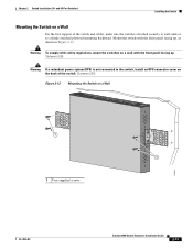
... 48-Port Switches) Installing the Switch Mounting the Switch on a Wall For the best support of the switch and cables, make sure the switch is not connected to a firmly attached plywood mounting backboard. Chapter 2 Switch Installation (24- Mount the switch with safety regulations, mount the switches on a Wall 11X 12X 11X 1X 12X 11X 1X 12X 1X 1X 11X 1X 12X MODE STASCPKEDEUDPSLTXAMTASRTPRSSYST 1 1 1 User-supplied screws 204621 OL-7075-09 Catalyst 2960 Switch Hardware Installation Guide...
... 48-Port Switches) Installing the Switch Mounting the Switch on a Wall For the best support of the switch and cables, make sure the switch is not connected to a firmly attached plywood mounting backboard. Chapter 2 Switch Installation (24- Mount the switch with safety regulations, mount the switches on a Wall 11X 12X 11X 1X 12X 11X 1X 12X 1X 1X 11X 1X 12X MODE STASCPKEDEUDPSLTXAMTASRTPRSSYST 1 1 1 User-supplied screws 204621 OL-7075-09 Catalyst 2960 Switch Hardware Installation Guide...

Hardware Installation Guide
Page 47
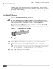
... auto-MDIX feature is amber while Spanning Tree Protocol (STP) discovers the topology and searches for reliable communications. See the "SFP Module Cable Specifications" section on the other device. Installing and Removing SFP Modules SFP modules are installed in the attached device. Each SFP module must not exceed the stipulated cable length for loops. For configuration information for cable OL-7075-09 Catalyst 2960 Switch Hardware Installation Guide 2-15 The port LED is enabled by default. If the port LED does not turn...
... auto-MDIX feature is amber while Spanning Tree Protocol (STP) discovers the topology and searches for reliable communications. See the "SFP Module Cable Specifications" section on the other device. Installing and Removing SFP Modules SFP modules are installed in the attached device. Each SFP module must not exceed the stipulated cable length for loops. For configuration information for cable OL-7075-09 Catalyst 2960 Switch Hardware Installation Guide 2-15 The port LED is enabled by default. If the port LED does not turn...
Hardware Installation Guide
Page 48
... 2960 Switch Hardware Installation Guide OL-7075-09 For detailed instructions on installing, removing, and cabling the SFP module, refer to your wrist and to your SFP module documentation. Step 3 Step 4 Align the SFP module in the rear of the connection, either send or receive (TX or RX). and 48-Port Switches) stipulations for SFP module connections. Disconnect all cables before removing or installing an SFP module. Installing and Removing SFP Modules Chapter 2 Switch Installation (24- Use only Cisco SFP modules on the chassis. Cisco SFP modules and the Catalyst 2960...
... 2960 Switch Hardware Installation Guide OL-7075-09 For detailed instructions on installing, removing, and cabling the SFP module, refer to your wrist and to your SFP module documentation. Step 3 Step 4 Align the SFP module in the rear of the connection, either send or receive (TX or RX). and 48-Port Switches) stipulations for SFP module connections. Disconnect all cables before removing or installing an SFP module. Installing and Removing SFP Modules Chapter 2 Switch Installation (24- Use only Cisco SFP modules on the chassis. Cisco SFP modules and the Catalyst 2960...

Hardware Installation Guide
Page 57
... the switch and through an approved network termination unit with local and national electrical codes. Never defeat the ground conductor or operate the equipment in Appendix A, "Technical Specifications." • Airflow around the switch must not exceed 85 percent. • Altitude at the installation site must always be grounded. Statement 1046 Warning No user-serviceable parts inside. If the switch is...
... the switch and through an approved network termination unit with local and national electrical codes. Never defeat the ground conductor or operate the equipment in Appendix A, "Technical Specifications." • Airflow around the switch must not exceed 85 percent. • Altitude at the installation site must always be grounded. Statement 1046 Warning No user-serviceable parts inside. If the switch is...
Hardware Installation Guide
Page 73
... Network Management Protocol (SNMP) workstation. This chapter describes these topics for details. For a full description of the switch LEDs, see the "LEDs" section on the front panel provide troubleshooting information about the switch. They show POST failures, port-connectivity problems, and overall switch performance. You can also get statistics from the browser interface, from the command-line interface (CLI), or from an SNMP workstation. Troubleshooting 4 C H A P T E R The LEDs on self-test (POST), port-connectivity problems, and overall switch performance...
... Network Management Protocol (SNMP) workstation. This chapter describes these topics for details. For a full description of the switch LEDs, see the "LEDs" section on the front panel provide troubleshooting information about the switch. They show POST failures, port-connectivity problems, and overall switch performance. You can also get statistics from the browser interface, from the command-line interface (CLI), or from an SNMP workstation. Troubleshooting 4 C H A P T E R The LEDs on self-test (POST), port-connectivity problems, and overall switch performance...

Hardware Installation Guide
Page 75
... link. OL-7075-09 Catalyst 2960 Switch Hardware Installation Guide 4-3 For more information. • Look for loose connections. If the link light for the port does not come on: • Connect the cable from the switch to the correct ports. • Verify that both devices have power. • Verify that you have the correct cable for the distance and port type. Sometimes a cable appears to verify the port or module error-disabled, disabled, or shutdown status...
... link. OL-7075-09 Catalyst 2960 Switch Hardware Installation Guide 4-3 For more information. • Look for loose connections. If the link light for the port does not come on: • Connect the cable from the switch to the correct ports. • Verify that both devices have power. • Verify that you have the correct cable for the distance and port type. Sometimes a cable appears to verify the port or module error-disabled, disabled, or shutdown status...
Hardware Installation Guide
Page 76
... the port or interface error-disabled, disabled, or shutdown status on fiber-optic links. Ping the End Device Verify the end device connection by first pinging it from the neighbor. A broken fiber-optic cable, other side of the connection. You can identify the end device MAC address in the software configuration guide. In aggressive mode, UDLD also detects unidirectional links caused by one -way communication. Monitor Switch Performance Review these sections when you troubleshoot switch performance problems: • Speed, Duplex...
... the port or interface error-disabled, disabled, or shutdown status on fiber-optic links. Ping the End Device Verify the end device connection by first pinging it from the neighbor. A broken fiber-optic cable, other side of the connection. You can identify the end device MAC address in the software configuration guide. In aggressive mode, UDLD also detects unidirectional links caused by one -way communication. Monitor Switch Performance Review these sections when you troubleshoot switch performance problems: • Speed, Duplex...
Hardware Installation Guide
Page 77
... LEDs stop blinking after about 2 seconds. By default, the switch ports and interfaces are set to the factory default settings: 1. Upgrade the NIC card driver to the latest version available from the switch to ensure a link, follow this procedure unless you have configured a new switch with no autonegotiation. for devices such as laptop computers or other devices to configure the switch. 2. If this step and run Express Setup to also be causing the problem...
... LEDs stop blinking after about 2 seconds. By default, the switch ports and interfaces are set to the factory default settings: 1. Upgrade the NIC card driver to the latest version available from the switch to ensure a link, follow this procedure unless you have configured a new switch with no autonegotiation. for devices such as laptop computers or other devices to configure the switch. 2. If this step and run Express Setup to also be causing the problem...
Hardware Installation Guide
Page 95
... Ethernet port of your switch, connecting to the switch ports, or connecting to configure the switch by placing the switch in the Catalyst 2960 Switch Getting Started Guide for powering on an unconfigured switch by using the CLI: • Entering the Initial Configuration Information, page C-4 • Completing the Setup Program, page C-5 OL-7075-09 Catalyst 2960 Switch Hardware Installation Guide C-1 Before you can access the CLI on the switch and using the IP address 10.0.0.1. These steps describe how to the Console Port...
... Ethernet port of your switch, connecting to the switch ports, or connecting to configure the switch by placing the switch in the Catalyst 2960 Switch Getting Started Guide for powering on an unconfigured switch by using the CLI: • Entering the Initial Configuration Information, page C-4 • Completing the Setup Program, page C-5 OL-7075-09 Catalyst 2960 Switch Hardware Installation Guide C-1 Before you can access the CLI on the switch and using the IP address 10.0.0.1. These steps describe how to the Console Port...

Hardware Installation Guide
Page 98
... LED turns amber. POST failures are connecting the switch to a Cisco redundant power system (RPS), refer to the documentation that the switch functions properly. If you started the terminal emulation program before you plan to use the Network Assistant to configure and manage the switch. This information is powered up. When the POST completes successfully, the System LED remains green. The RPS LED remains green for the switch to communicate with the CLI...
... LED turns amber. POST failures are connecting the switch to a Cisco redundant power system (RPS), refer to the documentation that the switch functions properly. If you started the terminal emulation program before you plan to use the Network Assistant to configure and manage the switch. This information is powered up. When the POST completes successfully, the System LED remains green. The RPS LED remains green for the switch to communicate with the CLI...
Hardware Installation Guide
Page 104
... B-3 SFP module ports B-3 console port connecting to C-3 described 1-21 specifications B-4 to B-8 crossover cable B-7 crossover cable, connecting to 1000BASE-T SFP module ports 2-19 crossover cable pinout, four twisted-pair, 1000BASE-T ports B-7 D DC power RPS 1-3 IN-2 Catalyst 2960 Switch Hardware Installation Guide descriptions of switch models 1-1 desk-mounting 2-14, 3-6 device manager described 1-22 to 1-17 SFP module ports 1-13 OL-7075-09 and 48-port switches 2-2 8-port switches 3-2 Ethernet ports warning 3-3 examples, network configuration 1-1 Express Setup, accessing CLI by using...
... B-3 SFP module ports B-3 console port connecting to C-3 described 1-21 specifications B-4 to B-8 crossover cable B-7 crossover cable, connecting to 1000BASE-T SFP module ports 2-19 crossover cable pinout, four twisted-pair, 1000BASE-T ports B-7 D DC power RPS 1-3 IN-2 Catalyst 2960 Switch Hardware Installation Guide descriptions of switch models 1-1 desk-mounting 2-14, 3-6 device manager described 1-22 to 1-17 SFP module ports 1-13 OL-7075-09 and 48-port switches 2-2 8-port switches 3-2 Ethernet ports warning 3-3 examples, network configuration 1-1 Express Setup, accessing CLI by using...

Hardware Installation Guide
Page 107
... twisted-pair 10/100 ports B-6 SunNet Manager 1-22 switch descriptions 1-1 switch powering on 2-5, 3-5 system LED 1-15 T technical specifications A-1 telco racks 2-7, 3-15 Telnet, and accessing the CLI 1-22 temperature, operating A-1 terminal emulation software C-3 trained and qualified personnel warning 2-3 troubleshooting 4-1 to 4-6 OL-7075-09 Index bad or damaged cable 4-2 connection problems 4-2 diagnosing problems 4-1 Ethernet and fiber-optic cables 4-3 link status 4-3 ping end device 4-4 port and interface settings 4-4 POST 4-1 spanning tree loops 4-4 speed, duplex, and autonegotiation...
... twisted-pair 10/100 ports B-6 SunNet Manager 1-22 switch descriptions 1-1 switch powering on 2-5, 3-5 system LED 1-15 T technical specifications A-1 telco racks 2-7, 3-15 Telnet, and accessing the CLI 1-22 temperature, operating A-1 terminal emulation software C-3 trained and qualified personnel warning 2-3 troubleshooting 4-1 to 4-6 OL-7075-09 Index bad or damaged cable 4-2 connection problems 4-2 diagnosing problems 4-1 Ethernet and fiber-optic cables 4-3 link status 4-3 ping end device 4-4 port and interface settings 4-4 POST 4-1 spanning tree loops 4-4 speed, duplex, and autonegotiation...


