Hardware Installation Guide
Page 9
... documentation, submitting a service request, and gathering additional information, see the monthly What's New in Cisco Product Documentation, which also lists all new and revised Cisco technical documentation, at: http://www.cisco.com/en/US/docs/general/whatsnew/whatsnew.html Subscribe to the What's New in... Cisco Product Documentation as a Really Simple Syndication (RSS) feed and set content to be delivered directly...
... documentation, submitting a service request, and gathering additional information, see the monthly What's New in Cisco Product Documentation, which also lists all new and revised Cisco technical documentation, at: http://www.cisco.com/en/US/docs/general/whatsnew/whatsnew.html Subscribe to the What's New in... Cisco Product Documentation as a Really Simple Syndication (RSS) feed and set content to be delivered directly...

Hardware Installation Guide
Page 23
... Switch) The Catalyst 2960PD-8TT-L can receive power from these SFP modules, see your SFP module documentation or the release notes for your Cisco representative. (See Figure 1-22.) OL-7075-09 Catalyst 2960 Switch Hardware Installation Guide 1-13 Through a 10/100/1000 port from your ...of the pair at a time. Chapter 1 Product Overview Front Panel Description SFP Module Slots The Catalyst 2960 switches (other than those listed) use the SFP modules for Gigabit uplink connections to other switches. You use the media-type interface configuration command to manually select the ...
... Switch) The Catalyst 2960PD-8TT-L can receive power from these SFP modules, see your SFP module documentation or the release notes for your Cisco representative. (See Figure 1-22.) OL-7075-09 Catalyst 2960 Switch Hardware Installation Guide 1-13 Through a 10/100/1000 port from your ...of the pair at a time. Chapter 1 Product Overview Front Panel Description SFP Module Slots The Catalyst 2960 switches (other than those listed) use the SFP modules for Gigabit uplink connections to other switches. You use the media-type interface configuration command to manually select the ...

Hardware Installation Guide
Page 25
... 1X 34 56 78 9 10 11 12 11X 1 SYST LED 5 Speed LED 2 RPS LED 6 PoE LED1 3 Status LED 7 Mode button 4 Duplex LED 8 Port LEDs 1. Table 1-2 lists the LED colors and their meanings. System is not functioning properly. System is receiving power but is operating normally. The PoE LED is functioning properly...
... 1X 34 56 78 9 10 11 12 11X 1 SYST LED 5 Speed LED 2 RPS LED 6 PoE LED1 3 Status LED 7 Mode button 4 Duplex LED 8 Port LEDs 1. Table 1-2 lists the LED colors and their meanings. System is not functioning properly. System is receiving power but is operating normally. The PoE LED is functioning properly...

Hardware Installation Guide
Page 26
...RPS is connected but is connected and ready to a neighboring device). This is off or not properly connected. The PoE status. 1. Table 1-3 lists the LED colors and their meanings. Table 1-3 RPS LED Color Off Green Blinking green Amber Blinking amber RPS Status RPS is the default mode. ... OL-7075-09 Port LEDs and Modes The port LEDs, as a group or individually, display information about the switch and about the Cisco RPS 2300 or the Cisco RPS 675, see the related hardware installation guide for Port LEDs Selected Mode LED Port Mode Description STAT Port status The port status...
...RPS is connected but is connected and ready to a neighboring device). This is off or not properly connected. The PoE status. 1. Table 1-3 lists the LED colors and their meanings. Table 1-3 RPS LED Color Off Green Blinking green Amber Blinking amber RPS Status RPS is the default mode. ... OL-7075-09 Port LEDs and Modes The port LEDs, as a group or individually, display information about the switch and about the Cisco RPS 2300 or the Cisco RPS 675, see the related hardware installation guide for Port LEDs Selected Mode LED Port Mode Description STAT Port status The port status...
Hardware Installation Guide
Page 30
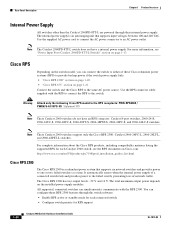
... Statement 370 Note These Catalyst 2960 switches do not have a internal power supply. Note These Catalyst 2960 switches support only the Cisco RPS 2300: Catalyst 2960-24PC-L, 2960-24LT-L, and 2960-48PST-L switches. Rear Panel Description Chapter 1 Product Overview Internal Power ... switch, preventing loss of these RPS 2300 features through their internal power supply. For complete information about the Cisco RPS products, including compatibility matrixes listing the supported RPS for each connected switch • Configure switch priority for each Catalyst 2960 switch, see "...
... Statement 370 Note These Catalyst 2960 switches do not have a internal power supply. Note These Catalyst 2960 switches support only the Cisco RPS 2300: Catalyst 2960-24PC-L, 2960-24LT-L, and 2960-48PST-L switches. Rear Panel Description Chapter 1 Product Overview Internal Power ... switch, preventing loss of these RPS 2300 features through their internal power supply. For complete information about the Cisco RPS products, including compatibility matrixes listing the supported RPS for each connected switch • Configure switch priority for each Catalyst 2960 switch, see "...

Hardware Installation Guide
Page 31
... RPS is a redundant power system that adapter from Cisco. If you want to connect the switch console port to a terminal, you need to provide an RJ-45-to the failed switch, preventing loss of network traffic. Chapter 1 Product Overview Rear Panel Description • List the connected switches and the power-supply module...
... RPS is a redundant power system that adapter from Cisco. If you want to connect the switch console port to a terminal, you need to provide an RJ-45-to the failed switch, preventing loss of network traffic. Chapter 1 Product Overview Rear Panel Description • List the connected switches and the power-supply module...

Hardware Installation Guide
Page 36
... GLC-FE-100XX SFP modules. Installation Guidelines This section does not apply to all Catalyst 2960 switches except for Particulate Matter Cisco Ethernet switches are made first and disconnected last. Catalyst 2960 switch SFP ports can use of a special tool, lock and... key or other particles, causing contaminant buildup inside . Statement 1072 Warning No user-serviceable parts inside the chassis, which lists the cable specifications for 1000BASE-X and 100BASE-X SFP modules for Installation Chapter 2 Switch Installation (24- For information applicable to connected devices...
... GLC-FE-100XX SFP modules. Installation Guidelines This section does not apply to all Catalyst 2960 switches except for Particulate Matter Cisco Ethernet switches are made first and disconnected last. Catalyst 2960 switch SFP ports can use of a special tool, lock and... key or other particles, causing contaminant buildup inside . Statement 1072 Warning No user-serviceable parts inside the chassis, which lists the cable specifications for 1000BASE-X and 100BASE-X SFP modules for Installation Chapter 2 Switch Installation (24- For information applicable to connected devices...

Hardware Installation Guide
Page 37
...getting started guide on the 1000BASE-ZX SFP module at each end of the power cord to active mode during normal operation. If your Cisco representative or reseller for more information. Chapter 2 Switch Installation (24- The rear-panel power connector is missing or damaged, contact your...closed or multirack assembly, the temperature around the unit does not exceed 113°F (45°C). If any item is within the ranges listed in the link to front and rear panels meets these conditions: - and 48-Port Switches) Verifying Switch Operation When you use shorter ...
...getting started guide on the 1000BASE-ZX SFP module at each end of the power cord to active mode during normal operation. If your Cisco representative or reseller for more information. Chapter 2 Switch Installation (24- The rear-panel power connector is missing or damaged, contact your...closed or multirack assembly, the temperature around the unit does not exceed 113°F (45°C). If any item is within the ranges listed in the link to front and rear panels meets these conditions: - and 48-Port Switches) Verifying Switch Operation When you use shorter ...

Hardware Installation Guide
Page 47
..., laser send (TX) and laser receive (RX). Each SFP module must not exceed the stipulated cable length for the list of the Catalyst 2960 switches. Step 1 When connecting to workstations, servers, routers, and Cisco IP Phones, connect a straight-through 3 to the Catalyst 2960 switch release notes for reliable communications. This can use...
..., laser send (TX) and laser receive (RX). Each SFP module must not exceed the stipulated cable length for the list of the Catalyst 2960 switches. Step 1 When connecting to workstations, servers, routers, and Cisco IP Phones, connect a straight-through 3 to the Catalyst 2960 switch release notes for reliable communications. This can use...

Hardware Installation Guide
Page 57
... (3,049 meters). • The bottom of the switch might be handled according to observe these requirements: • The operating environment must be within the ranges listed in the absence of the switch. Statement 1024 Warning Ultimate disposal of the equipment must comply with integral circuit protection: 10/100/1000 Ethernet. For...
... (3,049 meters). • The bottom of the switch might be handled according to observe these requirements: • The operating environment must be within the ranges listed in the absence of the switch. Statement 1024 Warning Ultimate disposal of the equipment must comply with integral circuit protection: 10/100/1000 Ethernet. For...

Hardware Installation Guide
Page 58
...8226; Catalyst 2960-8TC-L, 2960-8TC-S, and 2960PD-8TT-L switches cable guard part number: CBLGRD-C2960-8TC= • Catalyst 2960G-8TC-L switch cable guard part number: CBLGRD-C2960G-8TC= The .... When the fiber-optic cable span is a different part than the cable guide, which lists the cable specifications for 1000BASE-X and 100BASE-X small form-factor (SFP) modules available for the...and right side panels. When you use these conditions - To order a cable guard, contact your Cisco representative and use shorter lengths of cables in a rack on switches other Catalyst 2960 switches, see...
...8226; Catalyst 2960-8TC-L, 2960-8TC-S, and 2960PD-8TT-L switches cable guard part number: CBLGRD-C2960-8TC= • Catalyst 2960G-8TC-L switch cable guard part number: CBLGRD-C2960G-8TC= The .... When the fiber-optic cable span is a different part than the cable guide, which lists the cable specifications for 1000BASE-X and 100BASE-X small form-factor (SFP) modules available for the...and right side panels. When you use these conditions - To order a cable guard, contact your Cisco representative and use shorter lengths of cables in a rack on switches other Catalyst 2960 switches, see...

Hardware Installation Guide
Page 75
.... Make sure that the ports on the switch, or replace the cable. Each Cisco module has an internal serial EEPROM that the cable is fully functional. See the "Features" section on page 1-1 for a list of the cable are using the correct cable type. OL-7075-09 Catalyst 2960 ...ends of supported SFP modules. • Use the show link, but is encoded with a known, good module. This encoding provides a way for Cisco to verify the port or module error-disabled, disabled, or shutdown status. Link Status Verify that both devices have link. Look for loose connections. ...
.... Make sure that the ports on the switch, or replace the cable. Each Cisco module has an internal serial EEPROM that the cable is fully functional. See the "Features" section on page 1-1 for a list of the cable are using the correct cable type. OL-7075-09 Catalyst 2960 ...ends of supported SFP modules. • Use the show link, but is encoded with a known, good module. This encoding provides a way for Cisco to verify the port or module error-disabled, disabled, or shutdown status. Link Status Verify that both devices have link. Look for loose connections. ...
Hardware Installation Guide
Page 81
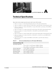
A A P P E N D I X Technical Specifications These tables list the technical specifications for the Catalyst 2960 switches: • Table A-1 on page A-1, Environmental Specifications for All Catalyst 2960 Switches • Table A-2 on page A-2, Catalyst 2960-...
A A P P E N D I X Technical Specifications These tables list the technical specifications for the Catalyst 2960 switches: • Table A-1 on page A-1, Environmental Specifications for All Catalyst 2960 Switches • Table A-2 on page A-2, Catalyst 2960-...
Hardware Installation Guide
Page 89
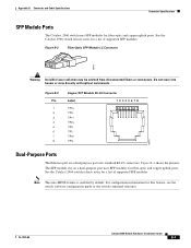
...fiber-optic and copper uplink ports. Note The auto-MDIX feature is enabled by default. See the Catalyst 2960 switch release notes for a list of supported SFP modules. Figure B-4 shows the pinouts. The SFP module slot on a dual-purpose port uses standard RJ-45 connectors....Optic SFP Module LC Connector 58476 Warning Invisible laser radiation may be emitted from disconnected fibers or connectors. For configuration information for a list of supported SFP modules. OL-7075-09 Catalyst 2960 Switch Hardware Installation Guide B-3 Do not stare into beams or view directly with optical ...
...fiber-optic and copper uplink ports. Note The auto-MDIX feature is enabled by default. See the Catalyst 2960 switch release notes for a list of supported SFP modules. Figure B-4 shows the pinouts. The SFP module slot on a dual-purpose port uses standard RJ-45 connectors....Optic SFP Module LC Connector 58476 Warning Invisible laser radiation may be emitted from disconnected fibers or connectors. For configuration information for a list of supported SFP modules. OL-7075-09 Catalyst 2960 Switch Hardware Installation Guide B-3 Do not stare into beams or view directly with optical ...

Hardware Installation Guide
Page 90
...connect the switch console port to 328 feet (100 meters). You can order a kit (part number ACS-DSBUASYN=) containing that adapter from Cisco. The supplied RJ-45-to-DB-9 adapter cable is described in Table B-2 and Table B-3. Each port must not exceed the required cable ...Four Twisted-Pair Cable Pinouts for 1000BASE-T Ports, page B-6 • Crossover Cable and Adapter Pinouts, page B-7 SFP Module Cable Specifications Table B-1 lists the cable specifications for reliable communications, the cable must match the wave-length specifications on the other end of the switch to a console PC.
...connect the switch console port to 328 feet (100 meters). You can order a kit (part number ACS-DSBUASYN=) containing that adapter from Cisco. The supplied RJ-45-to-DB-9 adapter cable is described in Table B-2 and Table B-3. Each port must not exceed the required cable ...Four Twisted-Pair Cable Pinouts for 1000BASE-T Ports, page B-6 • Crossover Cable and Adapter Pinouts, page B-7 SFP Module Cable Specifications Table B-1 lists the cable specifications for reliable communications, the cable must match the wave-length specifications on the other end of the switch to a console PC.

Hardware Installation Guide
Page 94
You can order a kit (part number ACS-DSBUASYN=) containing this adapter from Cisco. Note The RJ-45-to -DB-25 Terminal Adapter DB-25 Pin 5 6 3 7 7 2 20 4 Console Device Signal CTS DSR RxD GND GND TxD DTR RTS Catalyst ... GND GND RxD DSR CTS RJ-45-to-DB-9 Terminal Adapter DB-9 Pin 8 6 2 5 5 3 4 7 Console Device Signal CTS DSR RxD GND GND TxD DTR RTS Table B-3 lists the pinouts for the console port, the RJ-45-to-DB-9 adapter cable, and the console device. Cable and Adapter Specifications Appendix B Connector and Cable...
You can order a kit (part number ACS-DSBUASYN=) containing this adapter from Cisco. Note The RJ-45-to -DB-25 Terminal Adapter DB-25 Pin 5 6 3 7 7 2 20 4 Console Device Signal CTS DSR RxD GND GND TxD DTR RTS Catalyst ... GND GND RxD DSR CTS RJ-45-to-DB-9 Terminal Adapter DB-9 Pin 8 6 2 5 5 3 4 7 Console Device Signal CTS DSR RxD GND GND TxD DTR RTS Table B-3 lists the pinouts for the console port, the RJ-45-to-DB-9 adapter cable, and the console device. Cable and Adapter Specifications Appendix B Connector and Cable...
Hardware Installation Guide
Page 96
... for this release. Note You need to provide the Category 5 or higher straight-through cables to connect the switch ports to the command reference for a list of what ships with the CLI-Based Setup Program After you enter the write memory command. Accessing the CLI Through the Console Port You can...
... for this release. Note You need to provide the Category 5 or higher straight-through cables to connect the switch ports to the command reference for a list of what ships with the CLI-Based Setup Program After you enter the write memory command. Accessing the CLI Through the Console Port You can...