
Hardware Installation Guide
Page 3
... LEDs and Modes 1-16 Dual-Purpose Port LEDs 1-18 Cable Guard for the Catalyst 2960 8-Port Switches 1-19 Rear Panel Description 1-19 Internal Power Supply 1-20 Cisco RPS 1-20 Cisco RPS 2300 1-20 Cisco RPS 675 1-21 Console Port 1-21 Security Slots 1-21 Management Options 1-22 Network Configurations 1-22 Catalyst 2960 Switch Hardware Installation...
... LEDs and Modes 1-16 Dual-Purpose Port LEDs 1-18 Cable Guard for the Catalyst 2960 8-Port Switches 1-19 Rear Panel Description 1-19 Internal Power Supply 1-20 Cisco RPS 1-20 Cisco RPS 2300 1-20 Cisco RPS 675 1-21 Console Port 1-21 Security Slots 1-21 Management Options 1-22 Network Configurations 1-22 Catalyst 2960 Switch Hardware Installation...

Hardware Installation Guide
Page 11
...connect devices such as workstations, Cisco Wireless Access Points, Cisco IP Phones, and other network devices including servers, routers, and other network devices. These topics are included: • Features, page 1-1 • Front Panel Description, page 1-4 • Rear Panel Description, page 1-19 • Management... 2960-24-S Catalyst 2960-24TC-S Catalyst 2960-48TC-S Catalyst 2960-48TT-S Catalyst 2960-48PST-S Catalyst 2960-24PC-S Supported Software Image Description LAN-Lite 8 10/100BASE-TX Ethernet ports and 1 dual-purpose port (1 10/100/1000BASE-T copper port and 1 small form...
...connect devices such as workstations, Cisco Wireless Access Points, Cisco IP Phones, and other network devices including servers, routers, and other network devices. These topics are included: • Features, page 1-1 • Front Panel Description, page 1-4 • Rear Panel Description, page 1-19 • Management... 2960-24-S Catalyst 2960-24TC-S Catalyst 2960-48TC-S Catalyst 2960-48TT-S Catalyst 2960-48PST-S Catalyst 2960-24PC-S Supported Software Image Description LAN-Lite 8 10/100BASE-TX Ethernet ports and 1 dual-purpose port (1 10/100/1000BASE-T copper port and 1 small form...

Hardware Installation Guide
Page 12
...with a magnet, have security lock slots, and do not have a fan. Features Chapter 1 Product Overview Table 1-1 Catalyst 2960 Switch Model Descriptions (continued) Switch Model Catalyst 2960-24LC-S Catalyst 2960-8TC-L Catalyst 2960G-8TC-L Catalyst 2960PD-8TT-L Catalyst 2960-24LT-L Catalyst 2960-24PC-L Catalyst... the other Catalyst 2960 switches. See "Catalyst 2960 8-Port Switches" section on page 1-9 for these switch models. They can be mounted with Cisco prestandard PoE and IEEE 802.3af: • Catalyst 2960-24LC-S • Catalyst 2960-24LT-L • Catalyst 2960-24PC-L • Catalyst...
...with a magnet, have security lock slots, and do not have a fan. Features Chapter 1 Product Overview Table 1-1 Catalyst 2960 Switch Model Descriptions (continued) Switch Model Catalyst 2960-24LC-S Catalyst 2960-8TC-L Catalyst 2960G-8TC-L Catalyst 2960PD-8TT-L Catalyst 2960-24LT-L Catalyst 2960-24PC-L Catalyst... the other Catalyst 2960 switches. See "Catalyst 2960 8-Port Switches" section on page 1-9 for these switch models. They can be mounted with Cisco prestandard PoE and IEEE 802.3af: • Catalyst 2960-24LC-S • Catalyst 2960-24LT-L • Catalyst 2960-24PC-L • Catalyst...

Hardware Installation Guide
Page 14
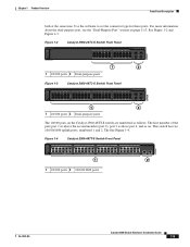
... on the Catalyst 2960-24TC-S and Catalyst 2960-48TC-S switches are numbered as the Catalyst 2960-24T-S switch. See Figure 1-1. Front Panel Description Chapter 1 Product Overview Front Panel Description These sections describe the switch front panels: • Catalyst 2960 Switch 24- and 48-Port Switches These sections describe the Catalyst 2960 24...
... on the Catalyst 2960-24TC-S and Catalyst 2960-48TC-S switches are numbered as the Catalyst 2960-24T-S switch. See Figure 1-1. Front Panel Description Chapter 1 Product Overview Front Panel Description These sections describe the switch front panels: • Catalyst 2960 Switch 24- and 48-Port Switches These sections describe the Catalyst 2960 24...
Hardware Installation Guide
Page 15
See Figure 1-2 and Figure 1-3. Chapter 1 Product Overview Front Panel Description both at the same time. For more information about the dual-purpose port, see the "Dual-Purpose Port" section on . This switch has two 10/...
See Figure 1-2 and Figure 1-3. Chapter 1 Product Overview Front Panel Description both at the same time. For more information about the dual-purpose port, see the "Dual-Purpose Port" section on . This switch has two 10/...

Hardware Installation Guide
Page 16
... PoE ports 3 Dual-purpose ports 2 10/100 ports Catalyst 2960 Switch Hardware Installation Guide 1-6 OL-7075-09 See Figure 1-7. See Figure 1-5 and Figure 1-6. Front Panel Description Chapter 1 Product Overview Catalyst 2960-24PC-L, 2960-24PC-S, 2960-24LC-S, 2960-24TC-L, 2960-48TC-L, 2960-24LT-L, 2960-24TT-L, 2960-48TT-L, 2960-48PST-L, and 2960-48PST...
... PoE ports 3 Dual-purpose ports 2 10/100 ports Catalyst 2960 Switch Hardware Installation Guide 1-6 OL-7075-09 See Figure 1-7. See Figure 1-5 and Figure 1-6. Front Panel Description Chapter 1 Product Overview Catalyst 2960-24PC-L, 2960-24PC-S, 2960-24LC-S, 2960-24TC-L, 2960-48TC-L, 2960-24LT-L, 2960-24TT-L, 2960-48TT-L, 2960-48PST-L, and 2960-48PST...
Hardware Installation Guide
Page 17
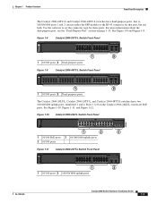
.../100/1000 uplink ports OL-7075-09 Catalyst 2960 Switch Hardware Installation Guide 1-7 Use the software to 8 on page 1-13. Chapter 1 Product Overview Front Panel Description The Catalyst 2960-24TC-L and Catalyst 2960-48TC-L switches have two 10/100/1000 uplink ports, numbered 1 and 2. See Figure 1-8 and Figure 1-9.
.../100/1000 uplink ports OL-7075-09 Catalyst 2960 Switch Hardware Installation Guide 1-7 Use the software to 8 on page 1-13. Chapter 1 Product Overview Front Panel Description The Catalyst 2960-24TC-L and Catalyst 2960-48TC-L switches have two 10/100/1000 uplink ports, numbered 1 and 2. See Figure 1-8 and Figure 1-9.

Hardware Installation Guide
Page 18
... ports 2 10/100/1000 uplink ports 3 SFP module slots Catalyst 2960G-24TC-L and Catalyst 2960G-48TC-L Switches The 10/100/1000 ports on . Front Panel Description Chapter 1 Product Overview Figure 1-12 Catalyst 2960-48TT-L Switch Front Panel 204609 SYST RPS STAT DUPLX SPEED MODE 1 2 1 10/100 ports 2 10/100/1000 uplink...
... ports 2 10/100/1000 uplink ports 3 SFP module slots Catalyst 2960G-24TC-L and Catalyst 2960G-48TC-L Switches The 10/100/1000 ports on . Front Panel Description Chapter 1 Product Overview Figure 1-12 Catalyst 2960-48TT-L Switch Front Panel 204609 SYST RPS STAT DUPLX SPEED MODE 1 2 1 10/100 ports 2 10/100/1000 uplink...

Hardware Installation Guide
Page 19
... switch can receive power from an optional AC power adapter that can also receive power from an upstream PoE switch. Chapter 1 Product Overview Front Panel Description Figure 1-15 Catalyst 2960G-24TC-L Switch Front Panel 204610 SYST RPS STAT DUPLX SPEED MODE 1 2 1 10/100/1000 ports 2 Dual-purpose ports Figure 1-16 Catalyst...
... switch can receive power from an optional AC power adapter that can also receive power from an upstream PoE switch. Chapter 1 Product Overview Front Panel Description Figure 1-15 Catalyst 2960G-24TC-L Switch Front Panel 204610 SYST RPS STAT DUPLX SPEED MODE 1 2 1 10/100/1000 ports 2 Dual-purpose ports Figure 1-16 Catalyst...

Hardware Installation Guide
Page 20
Front Panel Description Chapter 1 Product Overview Catalyst 2960-8TC-S, Catalyst 2960-8TC-L, and Catalyst 2960G-8TC -L Switches The console ports for the Catalyst 2960-8TC-S, Catalyst 2960-8TC-L, ...
Front Panel Description Chapter 1 Product Overview Catalyst 2960-8TC-S, Catalyst 2960-8TC-L, and Catalyst 2960G-8TC -L Switches The console ports for the Catalyst 2960-8TC-S, Catalyst 2960-8TC-L, ...

Hardware Installation Guide
Page 21
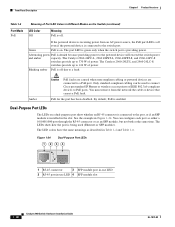
...crossover cable for the cables are described in Appendix B, "Connector and Cable Specifications." When the port is set to workstations, servers, routers, and Cisco IP Phones, be sure that the cable is a straight-through cable. In all cases, the attached device must be within 328 feet (100... settings of the attached device and advertises its own capabilities. Chapter 1 Product Overview Front Panel Description 10/100 Ports You can set the 10/100 ports to workstations, servers, routers, and Cisco IP Phones, be sure that the cable is a straight-through cable. You can use the...
...crossover cable for the cables are described in Appendix B, "Connector and Cable Specifications." When the port is set to workstations, servers, routers, and Cisco IP Phones, be sure that the cable is a straight-through cable. In all cases, the attached device must be within 328 feet (100... settings of the attached device and advertises its own capabilities. Chapter 1 Product Overview Front Panel Description 10/100 Ports You can set the 10/100 ports to workstations, servers, routers, and Cisco IP Phones, be sure that the cable is a straight-through cable. You can use the...

Hardware Installation Guide
Page 22
... might switch to the AC power source as an IEEE 802.3af-compliant powered device, a Cisco prestandard IP phone, or a Cisco prestandard Cisco access point, is also supported for Cisco IP Phones and Cisco Aironet Access Points. • Each of the PoE ports on the Catalyst 2960 switches deliver ...and 2960-24LC-S switches provide PoE support for redundant power. Warning Voltages that came with your IP phone or access point. Front Panel Description Chapter 1 Product Overview PoE Ports (Only Catalyst 2960 PoE Switches) This section applies only to the powered device. Avoid using such ...
... might switch to the AC power source as an IEEE 802.3af-compliant powered device, a Cisco prestandard IP phone, or a Cisco prestandard Cisco access point, is also supported for Cisco IP Phones and Cisco Aironet Access Points. • Each of the PoE ports on the Catalyst 2960 switches deliver ...and 2960-24LC-S switches provide PoE support for redundant power. Warning Voltages that came with your IP phone or access point. Front Panel Description Chapter 1 Product Overview PoE Ports (Only Catalyst 2960 PoE Switches) This section applies only to the powered device. Avoid using such ...

Hardware Installation Guide
Page 23
... uplink, see your SFP module documentation or the release notes for your Cisco representative. (See Figure 1-22.) OL-7075-09 Catalyst 2960 Switch Hardware Installation Guide 1-13 Each port is on the active connector. Chapter 1 Product Overview Front Panel Description SFP Module Slots The Catalyst 2960 switches (other switches. You use Gigabit...
... uplink, see your SFP module documentation or the release notes for your Cisco representative. (See Figure 1-22.) OL-7075-09 Catalyst 2960 Switch Hardware Installation Guide 1-13 Each port is on the active connector. Chapter 1 Product Overview Front Panel Description SFP Module Slots The Catalyst 2960 switches (other switches. You use Gigabit...

Hardware Installation Guide
Page 24
... LED: Catalyst 2960-24-S, Catalyst 2960-24TC-S, Catalyst 2960-48TT-S, Catalyst 2960-48TC-S. 1-14 Catalyst 2960 Switch Hardware Installation Guide OL-7075-09 Front Panel Description Chapter 1 Product Overview Figure 1-21 Connecting Through a 10/100/1000 Port SYST STAT DPLX SPD 1x 2x 3x 4x 5x 6x 7x 8x CONSOLE MODE...
... LED: Catalyst 2960-24-S, Catalyst 2960-24TC-S, Catalyst 2960-48TT-S, Catalyst 2960-48TC-S. 1-14 Catalyst 2960 Switch Hardware Installation Guide OL-7075-09 Front Panel Description Chapter 1 Product Overview Figure 1-21 Connecting Through a 10/100/1000 Port SYST STAT DPLX SPD 1x 2x 3x 4x 5x 6x 7x 8x CONSOLE MODE...

Hardware Installation Guide
Page 25
Chapter 1 Product Overview Figure 1-23 Catalyst 2960 Switch LEDs 8 Front Panel Description System LED 204612 1 2 3 4 5 6 SYST RPS STAT DUPLX SPEED PoE MODE 7 12 1X 34 56 78 9 10 11 12 11X 1 SYST LED 5 Speed LED 2 RPS LED 6 ...
Chapter 1 Product Overview Figure 1-23 Catalyst 2960 Switch LEDs 8 Front Panel Description System LED 204612 1 2 3 4 5 6 SYST RPS STAT DUPLX SPEED PoE MODE 7 12 1X 34 56 78 9 10 11 12 11X 1 SYST LED 5 Speed LED 2 RPS LED 6 ...

Hardware Installation Guide
Page 26
..., as a group or individually, display information about the switch and about the Cisco RPS 2300 or the Cisco RPS 675, see the related hardware installation guide for Port LEDs Selected Mode LED Port Mode Description STAT Port status The port status. The port operating speed: 10, 100, ...or 1000 Mb/s. RPS is the default mode. This is connected and ready to provide back-up power, if required. Contact Cisco Systems. The internal power supply in...
..., as a group or individually, display information about the switch and about the Cisco RPS 2300 or the Cisco RPS 675, see the related hardware installation guide for Port LEDs Selected Mode LED Port Mode Description STAT Port status The port status. The port operating speed: 10, 100, ...or 1000 Mb/s. RPS is the default mode. This is connected and ready to provide back-up power, if required. Contact Cisco Systems. The internal power supply in...

Hardware Installation Guide
Page 27
... present. Blinking green Activity. Blinking green Port is operating at 1000 Mb/s. Blinking green Port is operating at 1000 Mb/s. Chapter 1 Product Overview Front Panel Description Even if the PoE mode is not selected, the PoE LED shows PoE problems when they are in a fault condition. Table 1-5 PoE Mode LED Color...
... present. Blinking green Activity. Blinking green Port is operating at 1000 Mb/s. Blinking green Port is operating at 1000 Mb/s. Chapter 1 Product Overview Front Panel Description Even if the PoE mode is not selected, the PoE LED shows PoE problems when they are in a fault condition. Table 1-5 PoE Mode LED Color...
Hardware Installation Guide
Page 28
...). Green PoE is enabled. Alternating green PoE is providing power. The Catalyst 2960-24LT-L and 2960-24LC-S switches provide up to PoE ports. Front Panel Description Chapter 1 Product Overview Table 1-6 Port Mode PoE Meaning of Port LED Colors in Figure 1-24. The port LED is green only when the switch port... denied because providing power to 124 W of power. You must remove from an AC power source, the PoE port LED is being used to connect Cisco prestandard IP Phones or wireless access points or IEEE 802.3af-compliant devices to 370 W of power.
...). Green PoE is enabled. Alternating green PoE is providing power. The Catalyst 2960-24LT-L and 2960-24LC-S switches provide up to PoE ports. Front Panel Description Chapter 1 Product Overview Table 1-6 Port Mode PoE Meaning of Port LED Colors in Figure 1-24. The port LED is green only when the switch port... denied because providing power to 124 W of power. You must remove from an AC power source, the PoE port LED is being used to connect Cisco prestandard IP Phones or wireless access points or IEEE 802.3af-compliant devices to 370 W of power.
Hardware Installation Guide
Page 29
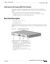
...do not have a fan. 4. OL-7075-09 Catalyst 2960 Switch Hardware Installation Guide 1-19 Chapter 1 Product Overview Rear Panel Description Cable Guard for an example of the Catalyst 2960-8TC-L, 2960G-8TC-L, 2960-8TC-S, and 2960PD-8TT-L switches and prevent them...order a cable guard, contact your Cisco representative using these part numbers: • CBLGRD-C2960-8TC: Catalyst 2960-8TC-L, 2960-8TC-S, and 2960PD-8TT-L switches • CBLGRD-C2960G-8TC: Cisco Catalyst 2960G-8TC switch Rear Panel Description • Internal Power Supply, page 1-20 • Cisco RPS, page 1-20 • Console...
...do not have a fan. 4. OL-7075-09 Catalyst 2960 Switch Hardware Installation Guide 1-19 Chapter 1 Product Overview Rear Panel Description Cable Guard for an example of the Catalyst 2960-8TC-L, 2960G-8TC-L, 2960-8TC-S, and 2960PD-8TT-L switches and prevent them...order a cable guard, contact your Cisco representative using these part numbers: • CBLGRD-C2960-8TC: Catalyst 2960-8TC-L, 2960-8TC-S, and 2960PD-8TT-L switches • CBLGRD-C2960G-8TC: Cisco Catalyst 2960G-8TC switch Rear Panel Description • Internal Power Supply, page 1-20 • Cisco RPS, page 1-20 • Console...
Hardware Installation Guide
Page 30
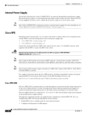
... not have a internal power supply. For more information, see the RPS documents on the installed power-supply modules. Rear Panel Description Chapter 1 Product Overview Internal Power Supply All switches other than the Catalyst 2960PD-8TT-L are powered through the switch software: &#...-24-S, 2960-24TC-S, 2960-48TC-S, 2960-48TT-S, 2960-48PST-S, 2960-24PC-S, and 2960-24LC-S switches. For complete information about the Cisco RPS products, including compatibility matrixes listing the supported RPS for each connected switch • Configure switch priority for each Catalyst 2960 switch,...
... not have a internal power supply. For more information, see the RPS documents on the installed power-supply modules. Rear Panel Description Chapter 1 Product Overview Internal Power Supply All switches other than the Catalyst 2960PD-8TT-L are powered through the switch software: &#...-24-S, 2960-24TC-S, 2960-48TC-S, 2960-48TT-S, 2960-48PST-S, 2960-24PC-S, and 2960-24LC-S switches. For complete information about the Cisco RPS products, including compatibility matrixes listing the supported RPS for each connected switch • Configure switch priority for each Catalyst 2960 switch,...