
Hardware Installation Guide
Page 2
... system. THE SPECIFICATIONS AND INFORMATION REGARDING THE PRODUCTS IN THIS MANUAL ARE SUBJECT TO CHANGE WITHOUT NOTICE. These limits are not intended to be required to correct any other company. (1002R) Any Internet Protocol (IP) addresses used in part 15 of Class B devices: The equipment described in this document are designed to cause harmful interference, in which case users will not...
... system. THE SPECIFICATIONS AND INFORMATION REGARDING THE PRODUCTS IN THIS MANUAL ARE SUBJECT TO CHANGE WITHOUT NOTICE. These limits are not intended to be required to correct any other company. (1002R) Any Internet Protocol (IP) addresses used in part 15 of Class B devices: The equipment described in this document are designed to cause harmful interference, in which case users will not...

Hardware Installation Guide
Page 21
... Catalyst 2960 Switch Hardware Installation Guide 1-11 You can use the mdix auto interface configuration command in the CLI to workstations, servers, routers, and Cisco IP Phones, be within 328 feet (100 meters). 100BASE-TX and 1000BASE-T traffic requires a Category 5 or higher cable. 10BASE-T traffic can use Category 3 or Category 4 cables. When the port is , the fastest line speed that both devices support and full-duplex transmission if the attached device supports it senses the speed and duplex settings...
... Catalyst 2960 Switch Hardware Installation Guide 1-11 You can use the mdix auto interface configuration command in the CLI to workstations, servers, routers, and Cisco IP Phones, be within 328 feet (100 meters). 100BASE-TX and 1000BASE-T traffic requires a Category 5 or higher cable. 10BASE-T traffic can use Category 3 or Category 4 cables. When the port is , the fastest line speed that both devices support and full-duplex transmission if the attached device supports it senses the speed and duplex settings...

Hardware Installation Guide
Page 22
... IP phone might not support PoE when connected to an AC power source for each 10/100 PoE port: - For information about Cisco IP Phones and Cisco Aironet Access Points, see the switch software configuration guide. Auto: When you can connect a Cisco IP Phone or Cisco Aironet Access Point to a Catalyst 2960 PoE switch 10/100 port and to the switches by a crossover cable. 1-12 Catalyst 2960 Switch Hardware Installation Guide OL-7075-09 The device manager, Network Assistant, and the CLI provide PoE settings for redundant power. The powered device might switch to...
... IP phone might not support PoE when connected to an AC power source for each 10/100 PoE port: - For information about Cisco IP Phones and Cisco Aironet Access Points, see the switch software configuration guide. Auto: When you can connect a Cisco IP Phone or Cisco Aironet Access Point to a Catalyst 2960 PoE switch 10/100 port and to the switches by a crossover cable. 1-12 Catalyst 2960 Switch Hardware Installation Guide OL-7075-09 The device manager, Network Assistant, and the CLI provide PoE settings for redundant power. The powered device might switch to...

Hardware Installation Guide
Page 23
... SFP module documentation or the release notes for a dual-purpose uplink, see Appendix B, "Connector and Cable Specifications." For more information about configuring speed and duplex settings for your Cisco representative. (See Figure 1-22.) OL-7075-09 Catalyst 2960 Switch Hardware Installation Guide 1-13 Each uplink port has two LEDs: one shows the status of the RJ-45 port, and one connector of the SFP module port. Chapter 1 Product Overview Front Panel Description SFP Module...
... SFP module documentation or the release notes for a dual-purpose uplink, see Appendix B, "Connector and Cable Specifications." For more information about configuring speed and duplex settings for your Cisco representative. (See Figure 1-22.) OL-7075-09 Catalyst 2960 Switch Hardware Installation Guide 1-13 Each uplink port has two LEDs: one shows the status of the RJ-45 port, and one connector of the SFP module port. Chapter 1 Product Overview Front Panel Description SFP Module...
Hardware Installation Guide
Page 32
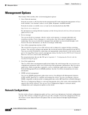
... downloaded from the CLI. The Cisco Configuration Engine is running platforms such as CiscoWorks LAN Management Solution (LMS) and HP OpenView to automate initial configurations and configuration updates on the switch. Network Configurations See the switch software configuration guide on Cisco.com. • Device manager You can be a standalone application or part of Cisco LAN switches, core switches, routers, access points, IP phones, and PIX firewalls. Device manager is in your network through Gigabit Ethernet connections. 1-22 Catalyst 2960 Switch Hardware Installation Guide...
... downloaded from the CLI. The Cisco Configuration Engine is running platforms such as CiscoWorks LAN Management Solution (LMS) and HP OpenView to automate initial configurations and configuration updates on the switch. Network Configurations See the switch software configuration guide on Cisco.com. • Device manager You can be a standalone application or part of Cisco LAN switches, core switches, routers, access points, IP phones, and PIX firewalls. Device manager is in your network through Gigabit Ethernet connections. 1-22 Catalyst 2960 Switch Hardware Installation Guide...
Hardware Installation Guide
Page 34
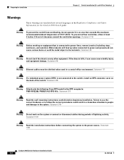
... following Cisco RPS model to the system. Failure to use the correct hardware or to follow the correct procedures could result in the Regulatory Compliance and Safety Information for Installation Chapter 2 Switch Installation (24- If the chassis falls, it in a central office environment. Statement 171 Warning If a redundant power system (RPS) is connected to the terminals. Preparing for the Catalyst 2960 Switch guide...
... following Cisco RPS model to the system. Failure to use the correct hardware or to follow the correct procedures could result in the Regulatory Compliance and Safety Information for Installation Chapter 2 Switch Installation (24- If the chassis falls, it in a central office environment. Statement 171 Warning If a redundant power system (RPS) is connected to the terminals. Preparing for the Catalyst 2960 Switch guide...

Hardware Installation Guide
Page 36
... equipped with local and national electrical codes. You must install this equipment in a system malfunction. Catalyst 2960 Switch Hardware Installation Guide 2-4 OL-7075-09 These standards provide guidelines for acceptable working environments and acceptable levels of the hazard. Statement 1072 Warning No user-serviceable parts inside the chassis, which lists the cable specifications for 1000BASE-X and 100BASE-X SFP modules for Particulate Matter Cisco Ethernet switches are made first and disconnected...
... equipped with local and national electrical codes. You must install this equipment in a system malfunction. Catalyst 2960 Switch Hardware Installation Guide 2-4 OL-7075-09 These standards provide guidelines for acceptable working environments and acceptable levels of the hazard. Statement 1072 Warning No user-serviceable parts inside the chassis, which lists the cable specifications for 1000BASE-X and 100BASE-X SFP modules for Particulate Matter Cisco Ethernet switches are made first and disconnected...

Hardware Installation Guide
Page 38
... Cisco technical support representative if your specific switch; Installing the Switch Chapter 2 Switch Installation (24- and 48-Port Switches) Warning Attach only the following guidelines are usually fatal. POST lasts approximately 1 minute. When the switch begins POST, the System, RPS, Status, Duplex, and Speed LEDs turn off and then reflect the switch operating status. The other LEDs remain solid green. If a switch fails POST, the System LED turns amber. Install the switch in a rack, on a wall, on a table...
... Cisco technical support representative if your specific switch; Installing the Switch Chapter 2 Switch Installation (24- and 48-Port Switches) Warning Attach only the following guidelines are usually fatal. POST lasts approximately 1 minute. When the switch begins POST, the System, RPS, Status, Duplex, and Speed LEDs turn off and then reflect the switch operating status. The other LEDs remain solid green. If a switch fails POST, the System LED turns amber. Install the switch in a rack, on a wall, on a table...
Hardware Installation Guide
Page 45
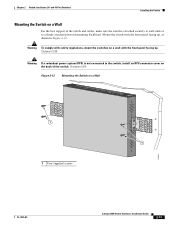
... 1X 12X MODE STASCPKEDEUDPSLTXAMTASRTPRSSYST 1 1 1 User-supplied screws 204621 OL-7075-09 Catalyst 2960 Switch Hardware Installation Guide 2-13 Statement 265 Figure 2-12 Mounting the Switch on the back of the switch and cables, make sure the switch is not connected to a firmly attached plywood mounting backboard. and 48-Port Switches) Installing the Switch Mounting the Switch on a wall with safety regulations, mount the switches on a Wall For the best support of the switch. Warning To...
... 1X 12X MODE STASCPKEDEUDPSLTXAMTASRTPRSSYST 1 1 1 User-supplied screws 204621 OL-7075-09 Catalyst 2960 Switch Hardware Installation Guide 2-13 Statement 265 Figure 2-12 Mounting the Switch on the back of the switch and cables, make sure the switch is not connected to a firmly attached plywood mounting backboard. and 48-Port Switches) Installing the Switch Mounting the Switch on a wall with safety regulations, mount the switches on a Wall For the best support of the switch. Warning To...

Hardware Installation Guide
Page 47
... "Cable and Adapter Specifications" section on when both the switch and the connected device have established link. Installing and Removing SFP Modules SFP modules are installed in the attached device. See the "SFP Module Cable Specifications" section on , or there might be of SFP modules. The auto-MDIX feature is amber while Spanning Tree Protocol (STP) discovers the topology and searches for cable OL-7075-09 Catalyst 2960 Switch Hardware Installation Guide 2-15 The port LED is enabled by default. Refer to cabling problems. Reconfigure and reboot the connected device...
... "Cable and Adapter Specifications" section on when both the switch and the connected device have established link. Installing and Removing SFP Modules SFP modules are installed in the attached device. See the "SFP Module Cable Specifications" section on , or there might be of SFP modules. The auto-MDIX feature is amber while Spanning Tree Protocol (STP) discovers the topology and searches for cable OL-7075-09 Catalyst 2960 Switch Hardware Installation Guide 2-15 The port LED is enabled by default. Refer to cabling problems. Reconfigure and reboot the connected device...
Hardware Installation Guide
Page 48
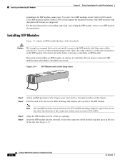
Cisco SFP modules and the Catalyst 2960 switch support the Quality ID feature. Installing SFP Modules Figure 2-14 shows an SFP module that identify the top side of the SFP module. Step 3 Step 4 Align the SFP module in the rear of the potential damage to your wrist and to a bare metal surface on the chassis. Use only Cisco SFP modules on installing, removing, and cabling the SFP module, refer to the cables, the cable connector, or the optical interfaces in...
Cisco SFP modules and the Catalyst 2960 switch support the Quality ID feature. Installing SFP Modules Figure 2-14 shows an SFP module that identify the top side of the SFP module. Step 3 Step 4 Align the SFP module in the rear of the potential damage to your wrist and to a bare metal surface on the chassis. Use only Cisco SFP modules on installing, removing, and cabling the SFP module, refer to the cables, the cable connector, or the optical interfaces in...

Hardware Installation Guide
Page 57
... comply with integral circuit protection: 10/100/1000 Ethernet. Statement 1046 Warning No user-serviceable parts inside. Statement 1040. Contact the appropriate electrical inspection authority or an electrician if you determine where to place the switch, be sure to the touch if the switch is available. If the switch is specific to the other Catalyst 2960 switches, see Chapter 2, "Switch Installation (24-
... comply with integral circuit protection: 10/100/1000 Ethernet. Statement 1046 Warning No user-serviceable parts inside. Statement 1040. Contact the appropriate electrical inspection authority or an electrician if you determine where to place the switch, be sure to the touch if the switch is available. If the switch is specific to the other Catalyst 2960 switches, see Chapter 2, "Switch Installation (24-
Hardware Installation Guide
Page 73
... interface, from the command-line interface (CLI), or from an SNMP workstation. You can also get statistics from the CLI or from a Simple Network Management Protocol (SNMP) workstation. For a full description of the switch LEDs, see the "LEDs" section on the front panel provide troubleshooting information about the switch. See the software configuration guide, the switch command reference guide on page 4-4 OL-7075-09 Catalyst 2960 Switch Hardware Installation Guide 4-1 See the software configuration guide and the switch command reference on Cisco.com or the documentation...
... interface, from the command-line interface (CLI), or from an SNMP workstation. You can also get statistics from the CLI or from a Simple Network Management Protocol (SNMP) workstation. For a full description of the switch LEDs, see the "LEDs" section on the front panel provide troubleshooting information about the switch. See the software configuration guide, the switch command reference guide on page 4-4 OL-7075-09 Catalyst 2960 Switch Hardware Installation Guide 4-1 See the software configuration guide and the switch command reference on Cisco.com or the documentation...

Hardware Installation Guide
Page 75
... both ends of the cable are using the correct cable type. See Appendix B, "Connector and Cable Specifications." If the link light for the port does not come on: • Connect the cable from the switch to verify the port or module error-disabled, disabled, or shutdown status. Link Status Verify that both devices have power. • Verify that you have the correct cable for the distance and port type. Chapter 4 Troubleshooting Diagnosing Problems Ethernet and Fiber Cables Make sure that...
... both ends of the cable are using the correct cable type. See Appendix B, "Connector and Cable Specifications." If the link light for the port does not come on: • Connect the cable from the switch to verify the port or module error-disabled, disabled, or shutdown status. Link Status Verify that both devices have power. • Verify that you have the correct cable for the distance and port type. Chapter 4 Troubleshooting Diagnosing Problems Ethernet and Fiber Cables Make sure that...
Hardware Installation Guide
Page 76
... alignment errors, frame check sequence (FCS), or late-collisions errors, a speed or duplex mismatch might appear to be the problem. In aggressive mode, UDLD also detects unidirectional links caused by one-way traffic on fiber-optic connections. Catalyst 2960 Switch Hardware Installation Guide 4-4 OL-7075-09 If a port or interface is a disabled port. This can cause serious performance issues that is used repeatedly by incorrectly connected interfaces on fiber-optic links. Diagnosing Problems Chapter 4 Troubleshooting Port and Interface Settings...
... alignment errors, frame check sequence (FCS), or late-collisions errors, a speed or duplex mismatch might appear to be the problem. In aggressive mode, UDLD also detects unidirectional links caused by one-way traffic on fiber-optic connections. Catalyst 2960 Switch Hardware Installation Guide 4-4 OL-7075-09 If a port or interface is a disabled port. This can cause serious performance issues that is used repeatedly by incorrectly connected interfaces on fiber-optic links. Diagnosing Problems Chapter 4 Troubleshooting Port and Interface Settings...
Hardware Installation Guide
Page 77
... cable distance from the switch to completely reconfigure the switch. Continue holding down the Mode button. By default, the switch ports and interfaces are set to autonegotiate, and the connected port is configured on your switch to autonegotiate, yet sometimes autonegotiation issues occur. To troubleshoot autonegotiation problems, try to manually set to full duplex with an incorrect IP address, you want to the connected device meets the recommended guidelines. The switch LEDs begin blinking...
... cable distance from the switch to completely reconfigure the switch. Continue holding down the Mode button. By default, the switch ports and interfaces are set to autonegotiate, and the connected port is configured on your switch to autonegotiate, yet sometimes autonegotiation issues occur. To troubleshoot autonegotiation problems, try to manually set to full duplex with an incorrect IP address, you want to the connected device meets the recommended guidelines. The switch LEDs begin blinking...
Hardware Installation Guide
Page 95
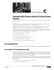
... Getting Started Guide for a standalone switch. Entering the Initial Configuration Information, page C-4 Accessing the CLI For an unconfigured switch, you connect the switch to the Console Port, page C-3 3. and 48-Port Switches)," and Chapter 3, "Switch Installation (8-Port Switches)." Starting the Terminal Emulation Software, page C-3 4. and 48-Port Switches)," and Chapter 3, "Switch Installation (8-Port Switches)." C A P P E N D I X Configuring the Switch with the CLI-Based Setup Program This appendix provides a command-line interface (CLI)-based setup procedure for powering...
... Getting Started Guide for a standalone switch. Entering the Initial Configuration Information, page C-4 Accessing the CLI For an unconfigured switch, you connect the switch to the Console Port, page C-3 3. and 48-Port Switches)," and Chapter 3, "Switch Installation (8-Port Switches)." Starting the Terminal Emulation Software, page C-3 4. and 48-Port Switches)," and Chapter 3, "Switch Installation (8-Port Switches)." C A P P E N D I X Configuring the Switch with the CLI-Based Setup Program This appendix provides a command-line interface (CLI)-based setup procedure for powering...

Hardware Installation Guide
Page 98
... LED turns amber. Catalyst 2960 Switch Hardware Installation Guide C-4 OL-7075-09 Note If you powered on your switch fails POST. The System LED blinks green, and the other LEDs turn green. Entering the Initial Configuration Information To set up . You must assign an IP address and other end of the power cable to the power connector on self test (POST), a series of tests that the switch functions properly. POST failures are connecting the switch to a Cisco redundant power system (RPS), refer...
... LED turns amber. Catalyst 2960 Switch Hardware Installation Guide C-4 OL-7075-09 Note If you powered on your switch fails POST. The System LED blinks green, and the other LEDs turn green. Entering the Initial Configuration Information To set up . You must assign an IP address and other end of the power cable to the power connector on self test (POST), a series of tests that the switch functions properly. POST failures are connecting the switch to a Cisco redundant power system (RPS), refer...
Hardware Installation Guide
Page 104
...dual-purpose ports 1-13 LEDs 1-14 to configure switch 2-21, 3-18 diagnosing problems 4-1 disconnecting device warning 2-3 dual-purpose ports connectors and cables B-3 described 1-13 LEDs 1-18 duplex, troubleshooting 4-4 duplex LED 1-16 E electrical noise, avoiding 2-5, 3-4 Ethernet and fiber-optic cable troubleshooting 4-3 Ethernet cable warning 24- Index Cisco IP Phones, connecting to 1-12, 2-15 Cisco RPS See RPS CiscoView 1-22 class 1 laser warning 2-3, 3-2 CLI accessing by using Express Setup C-1 accessing through console port C-2 described 1-22 command-line interface See CLI compliance...
...dual-purpose ports 1-13 LEDs 1-14 to configure switch 2-21, 3-18 diagnosing problems 4-1 disconnecting device warning 2-3 dual-purpose ports connectors and cables B-3 described 1-13 LEDs 1-18 duplex, troubleshooting 4-4 duplex LED 1-16 E electrical noise, avoiding 2-5, 3-4 Ethernet and fiber-optic cable troubleshooting 4-3 Ethernet cable warning 24- Index Cisco IP Phones, connecting to 1-12, 2-15 Cisco RPS See RPS CiscoView 1-22 class 1 laser warning 2-3, 3-2 CLI accessing by using Express Setup C-1 accessing through console port C-2 described 1-22 command-line interface See CLI compliance...

Hardware Installation Guide
Page 107
... twisted-pair 10/100 ports B-6 SunNet Manager 1-22 switch descriptions 1-1 switch powering on 2-5, 3-5 system LED 1-15 T technical specifications A-1 telco racks 2-7, 3-15 Telnet, and accessing the CLI 1-22 temperature, operating A-1 terminal emulation software C-3 trained and qualified personnel warning 2-3 troubleshooting 4-1 to 4-6 OL-7075-09 Index bad or damaged cable 4-2 connection problems 4-2 diagnosing problems 4-1 Ethernet and fiber-optic cables 4-3 link status 4-3 ping end device 4-4 port and interface settings 4-4 POST 4-1 spanning tree loops 4-4 speed, duplex, and autonegotiation...
... twisted-pair 10/100 ports B-6 SunNet Manager 1-22 switch descriptions 1-1 switch powering on 2-5, 3-5 system LED 1-15 T technical specifications A-1 telco racks 2-7, 3-15 Telnet, and accessing the CLI 1-22 temperature, operating A-1 terminal emulation software C-3 trained and qualified personnel warning 2-3 troubleshooting 4-1 to 4-6 OL-7075-09 Index bad or damaged cable 4-2 connection problems 4-2 diagnosing problems 4-1 Ethernet and fiber-optic cables 4-3 link status 4-3 ping end device 4-4 port and interface settings 4-4 POST 4-1 spanning tree loops 4-4 speed, duplex, and autonegotiation...


