
Hardware Installation Guide
Page 2
...If the interference stops, it off. CCDE, CCENT, CCSI, Cisco Eos, Cisco Explorer, Cisco HealthPresence, Cisco IronPort, the Cisco logo, Cisco Nurse Connect, Cisco Pulse, Cisco SensorBase, Cisco StackPower, Cisco StadiumVision, Cisco TelePresence, Cisco TrustSec, Cisco Unified Computing System, Cisco WebEx, DCE, Flip Channels, Flip for Good, Flip Mino...frequency energy and, if not installed and used in a residential installation. All rights reserved. THE SPECIFICATIONS AND INFORMATION REGARDING THE PRODUCTS IN THIS MANUAL ARE SUBJECT TO CHANGE WITHOUT NOTICE. THE SOFTWARE LICENSE ...
...If the interference stops, it off. CCDE, CCENT, CCSI, Cisco Eos, Cisco Explorer, Cisco HealthPresence, Cisco IronPort, the Cisco logo, Cisco Nurse Connect, Cisco Pulse, Cisco SensorBase, Cisco StackPower, Cisco StadiumVision, Cisco TelePresence, Cisco TrustSec, Cisco Unified Computing System, Cisco WebEx, DCE, Flip Channels, Flip for Good, Flip Mino...frequency energy and, if not installed and used in a residential installation. All rights reserved. THE SPECIFICATIONS AND INFORMATION REGARDING THE PRODUCTS IN THIS MANUAL ARE SUBJECT TO CHANGE WITHOUT NOTICE. THE SOFTWARE LICENSE ...

Hardware Installation Guide
Page 5
... 4-4 Speed, Duplex, and Autonegotiation 4-4 Autonegotiation and NIC Cards 4-5 Cabling Distance 4-5 Clearing the Switch IP Address and Configuration 4-5 Locating the Switch Serial Number 4-6 Technical Specifications A-1 Connector and Cable Specifications B-1 Connector Specifications B-1 10/100/1000 Ports B-1 Connecting to 1000BASE-T Devices B-2 SFP Module Ports B-3 Dual-Purpose Ports B-3 Catalyst 2960 Switch Hardware Installation Guide v Contents 4 C H A P T E R A A P P E N D I X B A P P E N D I X OL-7075...
... 4-4 Speed, Duplex, and Autonegotiation 4-4 Autonegotiation and NIC Cards 4-5 Cabling Distance 4-5 Clearing the Switch IP Address and Configuration 4-5 Locating the Switch Serial Number 4-6 Technical Specifications A-1 Connector and Cable Specifications B-1 Connector Specifications B-1 10/100/1000 Ports B-1 Connecting to 1000BASE-T Devices B-2 SFP Module Ports B-3 Dual-Purpose Ports B-3 Catalyst 2960 Switch Hardware Installation Guide v Contents 4 C H A P T E R A A P P E N D I X B A P P E N D I X OL-7075...

Hardware Installation Guide
Page 6
Contents C A P P E N D I X INDEX Console Port B-4 Cable and Adapter Specifications B-4 SFP Module Cable Specifications B-4 Two Twisted-Pair Cable Pinouts B-6 Four Twisted-Pair Cable Pinouts for 1000BASE-T Ports B-6 Crossover Cable and Adapter Pinouts B-7 Identifying a Crossover Cable B-7 Adapter Pinouts B-8 Configuring the ...
Contents C A P P E N D I X INDEX Console Port B-4 Cable and Adapter Specifications B-4 SFP Module Cable Specifications B-4 Two Twisted-Pair Cable Pinouts B-6 Four Twisted-Pair Cable Pinouts for 1000BASE-T Ports B-6 Crossover Cable and Adapter Pinouts B-7 Identifying a Crossover Cable B-7 Adapter Pinouts B-8 Configuring the ...

Hardware Installation Guide
Page 13
..., and 100BASE-FX SFP modules. For specific information about switch support for an optional Cisco RPS 2300 or Cisco RPS 675 redundant power system that operates on specific switches, see the Cisco Gigabit Ethernet Transceiver Modules Compatibility Matrix at this Cisco.com URL: http://www.cisco.com/en/US/docs/interfaces_modules/transceiver_modules/compatibility/...• 100BASE-BX • 100BASE-FX • 100BASE-LX The Catalyst 2960-24PC-L, 2960-24PC-S, 2960-24LC-S, 2960-24TC-L, 2960-48TC-L, 2960-48PST-L, 2960-48PST-S, 2960G-24TC-L, and 2960G-48TC-L switches support all the SFP modules.
..., and 100BASE-FX SFP modules. For specific information about switch support for an optional Cisco RPS 2300 or Cisco RPS 675 redundant power system that operates on specific switches, see the Cisco Gigabit Ethernet Transceiver Modules Compatibility Matrix at this Cisco.com URL: http://www.cisco.com/en/US/docs/interfaces_modules/transceiver_modules/compatibility/...• 100BASE-BX • 100BASE-FX • 100BASE-LX The Catalyst 2960-24PC-L, 2960-24PC-S, 2960-24LC-S, 2960-24TC-L, 2960-48TC-L, 2960-48PST-L, 2960-48PST-S, 2960G-24TC-L, and 2960G-48TC-L switches support all the SFP modules.

Hardware Installation Guide
Page 21
...these ports for copper Ethernet connections and configures the interfaces accordingly. When you connect the switch to workstations, servers, routers, and Cisco IP Phones, be sure that both devices support and full-duplex transmission if the attached device supports it ) and configures itself ... in full-duplex or half-duplex mode. When you can use the mdix auto interface configuration command in Appendix B, "Connector and Cable Specifications." You can use either a crossover or a straight-through cable for the cables are described in the command-line interface (CLI) to ...
...these ports for copper Ethernet connections and configures the interfaces accordingly. When you connect the switch to workstations, servers, routers, and Cisco IP Phones, be sure that both devices support and full-duplex transmission if the attached device supports it ) and configures itself ... in full-duplex or half-duplex mode. When you can use the mdix auto interface configuration command in Appendix B, "Connector and Cable Specifications." You can use either a crossover or a straight-through cable for the cables are described in the command-line interface (CLI) to ...

Hardware Installation Guide
Page 23
... connections to the back of the switch. You use fiber-optic cables with the switch, but you can order it from your Cisco representative. (See Figure 1-22.) OL-7075-09 Catalyst 2960 Switch Hardware Installation Guide 1-13 For more information about cabling requirements, ... speed and duplex settings for your SFP module documentation or the release notes for a dual-purpose uplink, see Appendix B, "Connector and Cable Specifications." However, you insert an SFP module. This external power adapter (PWR-A=) is on the active connector. For information about these sources: 1....
... connections to the back of the switch. You use fiber-optic cables with the switch, but you can order it from your Cisco representative. (See Figure 1-22.) OL-7075-09 Catalyst 2960 Switch Hardware Installation Guide 1-13 For more information about cabling requirements, ... speed and duplex settings for your SFP module documentation or the release notes for a dual-purpose uplink, see Appendix B, "Connector and Cable Specifications." However, you insert an SFP module. This external power adapter (PWR-A=) is on the active connector. For information about these sources: 1....

Hardware Installation Guide
Page 31
... is on the front panel rather than on the rear panel. For console port and adapter pinout information, see the "Connector and Cable Specifications" section on a left and right side panels. Security Slots The Catalyst 2960 8-port switches have security slots on the Catalyst 2960 8-port... status reports for the RPS power-supply module • Read and monitor backup, failure, and exception history Cisco RPS 675 The Cisco 675 RPS is a redundant power system that adapter from Cisco. It automatically senses when the internal power supply of a connected switch fails and provides power to -DB...
... is on the front panel rather than on the rear panel. For console port and adapter pinout information, see the "Connector and Cable Specifications" section on a left and right side panels. Security Slots The Catalyst 2960 8-port switches have security slots on the Catalyst 2960 8-port... status reports for the RPS power-supply module • Read and monitor backup, failure, and exception history Cisco RPS 675 The Cisco 675 RPS is a redundant power system that adapter from Cisco. It automatically senses when the internal power supply of a connected switch fails and provides power to -DB...

Hardware Installation Guide
Page 36
...applicable to the Catalyst 2960 8-port switches. Statement 1072 Warning No user-serviceable parts inside the chassis, which lists the cable specifications for 1000BASE-X and 100BASE-X SFP modules for the Catalyst 2960 switch. However, these requirements: • For 10/100/... switches. Statement 1074 Guidelines for acceptable working environments and acceptable levels of the hazard. These standards provide guidelines for Particulate Matter Cisco Ethernet switches are made aware of suspended particulate matter: • Network Equipment Building Systems (NEBS) GR-63-CORE •...
...applicable to the Catalyst 2960 8-port switches. Statement 1072 Warning No user-serviceable parts inside the chassis, which lists the cable specifications for 1000BASE-X and 100BASE-X SFP modules for the Catalyst 2960 switch. However, these requirements: • For 10/100/... switches. Statement 1074 Guidelines for acceptable working environments and acceptable levels of the hazard. These standards provide guidelines for Particulate Matter Cisco Ethernet switches are made aware of suspended particulate matter: • Network Equipment Building Systems (NEBS) GR-63-CORE •...

Hardware Installation Guide
Page 37
...8226; Temperature around the unit does not exceed 113°F (45°C). Note When you install the switch in Appendix A, "Technical Specifications." • Clearance to insert an inline optical attenuator in standby mode. OL-7075-09 Catalyst 2960 Switch Hardware Installation Guide 2-5 You...8226; The operating environment must be greater than normal room temperature. See Chapter 3, "Switch Installation (8-Port Switches)," and see the Cisco RPS documentation for more information. Box Contents The switch getting started guide on the switch, and connect the other devices that the...
...8226; Temperature around the unit does not exceed 113°F (45°C). Note When you install the switch in Appendix A, "Technical Specifications." • Clearance to insert an inline optical attenuator in standby mode. OL-7075-09 Catalyst 2960 Switch Hardware Installation Guide 2-5 You...8226; The operating environment must be greater than normal room temperature. See Chapter 3, "Switch Installation (8-Port Switches)," and see the Cisco RPS documentation for more information. Box Contents The switch getting started guide on the switch, and connect the other devices that the...

Hardware Installation Guide
Page 38
... successfully, the System LED remains green. The other LEDs remain solid green. Installing the Switch This section applies to all 24- The following Cisco RPS model to the RPS receptacle: PWR-RPS2300, PWR675-AC-RPS-N1=. The System LED blinks green, and the other LEDs turn green.... mounting or servicing this unit in a rack, you must take special precautions to ensure that the system remains stable. Call Cisco technical support representative if your specific switch; The illustrations in the rack. Statement 370 As the switch powers on, it is the only unit in the rack...
... successfully, the System LED remains green. The other LEDs remain solid green. Installing the Switch This section applies to all 24- The following Cisco RPS model to the RPS receptacle: PWR-RPS2300, PWR675-AC-RPS-N1=. The System LED blinks green, and the other LEDs turn green.... mounting or servicing this unit in a rack, you must take special precautions to ensure that the system remains stable. Call Cisco technical support representative if your specific switch; The illustrations in the rack. Statement 370 As the switch powers on, it is the only unit in the rack...

Hardware Installation Guide
Page 47
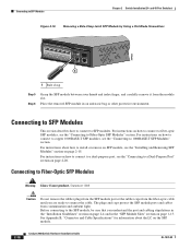
... must be sure to use a crossover cable. (See the "Cable and Adapter Specifications" section on page B-4 for the list of the Catalyst 2960 switches. Step 1 When connecting to workstations, servers, routers, and Cisco IP Phones, connect a straight-through 3 to the Catalyst 2960 switch release notes ...adapter installed in SFP module slots on the other device. The port LED is enabled by default. See the "SFP Module Cable Specifications" section on when both the switch and the connected device have established link. The auto-MDIX feature is amber while Spanning Tree Protocol...
... must be sure to use a crossover cable. (See the "Cable and Adapter Specifications" section on page B-4 for the list of the Catalyst 2960 switches. Step 1 When connecting to workstations, servers, routers, and Cisco IP Phones, connect a straight-through 3 to the Catalyst 2960 switch release notes ...adapter installed in SFP module slots on the other device. The port LED is enabled by default. See the "SFP Module Cable Specifications" section on when both the switch and the connected device have established link. The auto-MDIX feature is amber while Spanning Tree Protocol...
Hardware Installation Guide
Page 50
... connect the cable. Before connecting to the SFP module, be sure that you are ready to 1000BASE-T SFP Modules" section. See Appendix B, "Connector and Cable Specifications" for information about how to install or remove an SFP module, see the "Installing and Removing SFP Modules" section on how to connect to copper...
... connect the cable. Before connecting to the SFP module, be sure that you are ready to 1000BASE-T SFP Modules" section. See Appendix B, "Connector and Cable Specifications" for information about how to install or remove an SFP module, see the "Installing and Removing SFP Modules" section on how to connect to copper...

Hardware Installation Guide
Page 55
... perform the procedures in an area that ensures proper operation. Warning To prevent the switch from overheating, do not operate it in this chapter is specific to the switch, see Chapter 2, "Switch Installation (24- 3 C H A P T E R Switch Installation (8-Port Switches) This chapter describes how to start your switch and how to install the...
... perform the procedures in an area that ensures proper operation. Warning To prevent the switch from overheating, do not operate it in this chapter is specific to the switch, see Chapter 2, "Switch Installation (24- 3 C H A P T E R Switch Installation (8-Port Switches) This chapter describes how to start your switch and how to install the...

Hardware Installation Guide
Page 57
... that exceeds normal room temperature (such as in a closet, in a cabinet, or in a closed environment or in Appendix A, "Technical Specifications." • Airflow around the unit does not exceed 113°F (45°C). Statement 1024 Warning Ultimate disposal of a suitably installed ground conductor...an electrician if you allow at its maximum temperature 113°F (45°C) and is in an environment that suitable grounding is specific to the other Catalyst 2960 switches, see Chapter 2, "Switch Installation (24- Never defeat the ground conductor or operate the equipment...
... that exceeds normal room temperature (such as in a closet, in a cabinet, or in a closed environment or in Appendix A, "Technical Specifications." • Airflow around the unit does not exceed 113°F (45°C). Statement 1024 Warning Ultimate disposal of a suitably installed ground conductor...an electrician if you allow at its maximum temperature 113°F (45°C) and is in an environment that suitable grounding is specific to the other Catalyst 2960 switches, see Chapter 2, "Switch Installation (24- Never defeat the ground conductor or operate the equipment...

Hardware Installation Guide
Page 58
... Catalyst 2960 8-port switches. and 48-Port Switches)." To order a cable guard, contact your Cisco representative and use shorter lengths of single-mode fiber-optic cable, you should insert a 5-decibel ... • Catalyst 2960-8TC-L, 2960-8TC-S, and 2960PD-8TT-L switches cable guard part number: CBLGRD-C2960-8TC= • Catalyst 2960G-8TC-L switch cable guard part number: CBLGRD-C2960G-8TC= The cable ... Clearance to connected devices must be 328 feet (100 meters). • The cables meet the specifications in Table B-1 on page B-5, which you can reach from the AC power outlet to avoid ...
... Catalyst 2960 8-port switches. and 48-Port Switches)." To order a cable guard, contact your Cisco representative and use shorter lengths of single-mode fiber-optic cable, you should insert a 5-decibel ... • Catalyst 2960-8TC-L, 2960-8TC-S, and 2960PD-8TT-L switches cable guard part number: CBLGRD-C2960-8TC= • Catalyst 2960G-8TC-L switch cable guard part number: CBLGRD-C2960G-8TC= The cable ... Clearance to connected devices must be 328 feet (100 meters). • The cables meet the specifications in Table B-1 on page B-5, which you can reach from the AC power outlet to avoid ...

Hardware Installation Guide
Page 59
... should power on the switch, connect one end of tests that runs automatically to an AC power outlet. If any item is specific to rack-mount the switch. The System LED blinks green, and the other end of the power cord to ensure that the ...or on a desk, a shelf, or a wall, you need to supply a number-2 Phillips screwdriver to the Catalyst 2960 8-port switches. You can receive power from Cisco. The other Catalyst 2960 switches, see Chapter 2, "Switch Installation (24- or Shelf-Mounting (without Mounting Screws), page 3-6 • Desk- Chapter 3 Switch Installation (8-...
... should power on the switch, connect one end of tests that runs automatically to an AC power outlet. If any item is specific to rack-mount the switch. The System LED blinks green, and the other end of the power cord to ensure that the ...or on a desk, a shelf, or a wall, you need to supply a number-2 Phillips screwdriver to the Catalyst 2960 8-port switches. You can receive power from Cisco. The other Catalyst 2960 switches, see Chapter 2, "Switch Installation (24- or Shelf-Mounting (without Mounting Screws), page 3-6 • Desk- Chapter 3 Switch Installation (8-...

Hardware Installation Guide
Page 60
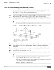
... the desk or shelf, do not want to use the mounting screws, follow these tasks to the Catalyst 2960 8-port switches. After the switch is specific to complete the installation: 1.
... the desk or shelf, do not want to use the mounting screws, follow these tasks to the Catalyst 2960 8-port switches. After the switch is specific to complete the installation: 1.
Hardware Installation Guide
Page 61
... or shelf with mounting screws. Use a 0.144-inch (3.7 mm) or a #27 drill bit to the top of the desk or shelf after the switch is specific to a desk or shelf with proper clearance. Remove the screw template from each other Catalyst 2960 switches, see Chapter 2, "Switch Installation (24- Note We strongly...
... or shelf with mounting screws. Use a 0.144-inch (3.7 mm) or a #27 drill bit to the top of the desk or shelf after the switch is specific to a desk or shelf with proper clearance. Remove the screw template from each other Catalyst 2960 switches, see Chapter 2, "Switch Installation (24- Note We strongly...
Hardware Installation Guide
Page 62
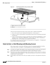
... MODE CONSOLE 1x 2x 3x 4x 5x 6x 7x 8x Catalyst 296S0eries 1 1 3 204626 2 1 Slides on this way 3 Desk or shelf 2 Screws After the switch is specific to the Catalyst 2960 8-port switches. See the switch getting started guide for instructions. 3. Catalyst 2960 Switch Hardware Installation Guide 3-8 OL-7075-09 For configuration...
... MODE CONSOLE 1x 2x 3x 4x 5x 6x 7x 8x Catalyst 296S0eries 1 1 3 204626 2 1 Slides on this way 3 Desk or shelf 2 Screws After the switch is specific to the Catalyst 2960 8-port switches. See the switch getting started guide for instructions. 3. Catalyst 2960 Switch Hardware Installation Guide 3-8 OL-7075-09 For configuration...
Hardware Installation Guide
Page 65
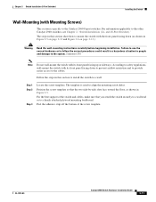
... panel facing down (as shown in this section show how to mount the switch with its front panel facing up or sideways. The template is specific to the Catalyst 2960 8-port switches. Follow the steps in Figure 3-5. Peel the adhesive strip off the bottom of the switch and cables, make sure...
... panel facing down (as shown in this section show how to mount the switch with its front panel facing up or sideways. The template is specific to the Catalyst 2960 8-port switches. Follow the steps in Figure 3-5. Peel the adhesive strip off the bottom of the switch and cables, make sure...
