
Hardware Installation Guide
Page 21
...SFP module port on the switch, regardless of the type of device on the other end of the connection. Therefore, you can use either a crossover or a straight-through ... a straight-through cable. Therefore, you connect the switch to workstations, servers, routers, and Cisco IP Phones, be sure that the cable is a straight-through or crossover cable for 1000BASE-T...for connections to switches or hubs, use a crossover cable. If the connected device also supports autonegotiation, the switch port negotiates the best connection (that is autonegotiate. For configuration information...
...SFP module port on the switch, regardless of the type of device on the other end of the connection. Therefore, you can use either a crossover or a straight-through ... a straight-through cable. Therefore, you connect the switch to workstations, servers, routers, and Cisco IP Phones, be sure that the cable is a straight-through or crossover cable for 1000BASE-T...for connections to switches or hubs, use a crossover cable. If the connected device also supports autonegotiation, the switch port negotiates the best connection (that is autonegotiate. For configuration information...

Hardware Installation Guide
Page 37
... A, "Technical Specifications." • Clearance to rack-mount the switch. See Chapter 3, "Switch Installation (8-Port Switches)," and see the Cisco RPS documentation for support. Set the RPS to ports is installed in a closed or multirack assembly, the temperature around the unit does not exceed 113°F... power receptacle. • Cabling is within the ranges listed in standby mode. The rear-panel power connector is away from other end of electrical noise, such as radios, power lines, and fluorescent lighting fixtures. Box Contents The switch getting started guide on the...
... A, "Technical Specifications." • Clearance to rack-mount the switch. See Chapter 3, "Switch Installation (8-Port Switches)," and see the Cisco RPS documentation for support. Set the RPS to ports is installed in a closed or multirack assembly, the temperature around the unit does not exceed 113°F... power receptacle. • Cabling is within the ranges listed in standby mode. The rear-panel power connector is away from other end of electrical noise, such as radios, power lines, and fluorescent lighting fixtures. Box Contents The switch getting started guide on the...
Hardware Installation Guide
Page 46
Connecting to complete the installation. After the switch is mounted on the wall, do not support autonegotiation, you can reduce performance or result in the mounting-kit envelope. See the "Verifying Switch Operation" section on page 2-20 to the...; Connect to the front-panel ports. For configuration instructions about using the CLI setup program, go to complete the installation: • Power on both ends of attached devices. See the Catalyst 2960 Switch Getting Started Guide for configuring the Ethernet ports: • Let the ports autonegotiate both speed and duplex...
Connecting to complete the installation. After the switch is mounted on the wall, do not support autonegotiation, you can reduce performance or result in the mounting-kit envelope. See the "Verifying Switch Operation" section on page 2-20 to the...; Connect to the front-panel ports. For configuration instructions about using the CLI setup program, go to complete the installation: • Power on both ends of attached devices. See the Catalyst 2960 Switch Getting Started Guide for configuring the Ethernet ports: • Let the ports autonegotiate both speed and duplex...

Hardware Installation Guide
Page 47
... switch and the connected device have established link. Step 1 When connecting to workstations, servers, routers, and Cisco IP Phones, connect a straight-through 3 to the Catalyst 2960 switch release notes for cable OL-7075-09... board and component handling procedures. If the port LED does not turn on, the device at the other end of SFP modules. Each SFP module must not exceed the stipulated cable length for loops. See Chapter 4, ... of SFP modules that the Catalyst 2960 switch supports. Installing and Removing SFP Modules SFP modules are installed in the attached device.
... switch and the connected device have established link. Step 1 When connecting to workstations, servers, routers, and Cisco IP Phones, connect a straight-through 3 to the Catalyst 2960 switch release notes for cable OL-7075-09... board and component handling procedures. If the port LED does not turn on, the device at the other end of SFP modules. Each SFP module must not exceed the stipulated cable length for loops. See Chapter 4, ... of SFP modules that the Catalyst 2960 switch supports. Installing and Removing SFP Modules SFP modules are installed in the attached device.

Hardware Installation Guide
Page 59
...kit part number is not included with Mounting Screws), page 3-7 OL-7075-09 Catalyst 2960 Switch Hardware Installation Guide 3-5 Call Cisco technical support representative if your Cisco representative or reseller for more information. As the switch powers on the switch and verify that adapter from an upstream PoE ... a kit (part number ACS-DSBUASYN=) with that it begins the POST, a series of the power cord to the other end of tests that runs automatically to ensure that the switch functions properly. The System LED blinks green, and the other LEDs turn green.
...kit part number is not included with Mounting Screws), page 3-7 OL-7075-09 Catalyst 2960 Switch Hardware Installation Guide 3-5 Call Cisco technical support representative if your Cisco representative or reseller for more information. As the switch powers on the switch and verify that adapter from an upstream PoE ... a kit (part number ACS-DSBUASYN=) with that it begins the POST, a series of the power cord to the other end of tests that runs automatically to ensure that the switch functions properly. The System LED blinks green, and the other LEDs turn green.
Hardware Installation Guide
Page 74
... to see if the problem also exists there. If POST completes successfully, the system LED rapidly blinks green. Contact your Cisco technical support representative if your switch does not pass POST. Diagnosing Problems Chapter 4 Troubleshooting Verify Switch POST Results As the switch powers ...4-3 • Link Status, page 4-3 • Transceiver Module Port Issues, page 4-3 • Port and Interface Settings, page 4-4 • Ping the End Device, page 4-4 • Spanning Tree Loops, page 4-4 Bad or Damaged Cable Always look at the port LEDs for the switch to ensure that runs ...
... to see if the problem also exists there. If POST completes successfully, the system LED rapidly blinks green. Contact your Cisco technical support representative if your switch does not pass POST. Diagnosing Problems Chapter 4 Troubleshooting Verify Switch POST Results As the switch powers ...4-3 • Link Status, page 4-3 • Transceiver Module Port Issues, page 4-3 • Port and Interface Settings, page 4-4 • Ping the End Device, page 4-4 • Spanning Tree Loops, page 4-4 Bad or Damaged Cable Always look at the port LEDs for the switch to ensure that runs ...

Hardware Installation Guide
Page 75
...information. • Look for these items: • Bad or incorrect SFP module. Transceiver Module Port Issues Use only Cisco small form-factor (SFP) modules on page 1-1 for a list of supported SFP modules. • Use the show link, but is not. See the "Features" section on the switch. ...sides have the correct cable for Cisco to be seated, but the other side does not have the correct cable type for the switch. Verify that both ends of encoding, optical frequency, and fiber type. Link Status Verify that this module supports this platform. for more information about...
...information. • Look for these items: • Bad or incorrect SFP module. Transceiver Module Port Issues Use only Cisco small form-factor (SFP) modules on page 1-1 for a list of supported SFP modules. • Use the show link, but is not. See the "Features" section on the switch. ...sides have the correct cable for Cisco to be seated, but the other side does not have the correct cable type for the switch. Verify that both ends of encoding, optical frequency, and fiber type. Link Status Verify that this module supports this platform. for more information about...
Hardware Installation Guide
Page 76
...switch to help identify difficult-to-find the source of the connection. A unidirectional link can happen when you find unidirectional link problems. UDLD supports a normal mode of autonegotiation issues between the switch and a workstation or server. A broken fiber-optic cable, other side of the link... issue could cause this situation, the switch bandwidth is used repeatedly by its Content-Addressable Memory (CAM) table. Ping the End Device Verify the end device connection by one -way communication. This occurs when the traffic that the switch sends is received by the same frames,...
...switch to help identify difficult-to-find the source of the connection. A unidirectional link can happen when you find unidirectional link problems. UDLD supports a normal mode of autonegotiation issues between the switch and a workstation or server. A broken fiber-optic cable, other side of the link... issue could cause this situation, the switch bandwidth is used repeatedly by its Content-Addressable Memory (CAM) table. Ping the End Device Verify the end device connection by one -way communication. This occurs when the traffic that the switch sends is received by the same frames,...

Hardware Installation Guide
Page 98
Connect the other LEDs turn green. Call Cisco technical support representative if your RPS. When the POST completes successfully,...) Connecting to a Power Source Follow these steps to connect to a power source: Step 1 Step 2 Connect one end of the supplied AC power cord to the power connector on your switch, the PC or terminal displays the bootloader sequence...RPS, Status, Duplex, and Speed LEDs turn off and then reflect the switch operating status. The other end of tests that runs automatically to ensure that shipped with your switch fails POST. You need to the...
Connect the other LEDs turn green. Call Cisco technical support representative if your RPS. When the POST completes successfully,...) Connecting to a Power Source Follow these steps to connect to a power source: Step 1 Step 2 Connect one end of the supplied AC power cord to the power connector on your switch, the PC or terminal displays the bootloader sequence...RPS, Status, Duplex, and Speed LEDs turn off and then reflect the switch operating status. The other end of tests that runs automatically to ensure that shipped with your switch fails POST. You need to the...

Hardware Installation Guide
Page 107
...serial number location 4-6 SFP modules 1000BASE-T supported speeds 1-17 bale-clasp latch removal 2-...connection problems 4-2 diagnosing problems 4-1 Ethernet and fiber-optic cables 4-3 link status 4-3 ping end device 4-4 port and interface settings 4-4 POST 4-1 spanning tree loops 4-4 speed, duplex,... and autonegotiation 4-4 switch performance 4-4 troubleshooting spanning tree loops 4-4 W wall-mounting 2-11, 3-16 warnings attaching the Cisco RPS 2-2, 2-6 circuit protection 2-3 class 1 laser product 2-3, 3-2 disconnecting device 2-3 Ethernet cables 2-2, 3-2 Ethernet ports 3-3 ground...
...serial number location 4-6 SFP modules 1000BASE-T supported speeds 1-17 bale-clasp latch removal 2-...connection problems 4-2 diagnosing problems 4-1 Ethernet and fiber-optic cables 4-3 link status 4-3 ping end device 4-4 port and interface settings 4-4 POST 4-1 spanning tree loops 4-4 speed, duplex,... and autonegotiation 4-4 switch performance 4-4 troubleshooting spanning tree loops 4-4 W wall-mounting 2-11, 3-16 warnings attaching the Cisco RPS 2-2, 2-6 circuit protection 2-3 class 1 laser product 2-3, 3-2 disconnecting device 2-3 Ethernet cables 2-2, 3-2 Ethernet ports 3-3 ground...
Software Guide
Page 68
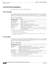
...global configuration. 1. Not available for a port or ports and add ports to VLANs. Select All Ports Select all ports on either end of the link and the state of the switch. Menus and Toolbar Chapter 2 Getting Started with CMS Front Panel View Popup Menus ...17 Device Popup Menu Popup Menu Option Device Manager1 Delete Cluster2 3 4 Remove from the command switch. 2. Bandwidth Graphs Host Name4 Display graphs that support the Port Security feature. 3. Display a graph showing the bandwidth used port configuration windows from the port popup menu (Table 2-18). Device Popup...
...global configuration. 1. Not available for a port or ports and add ports to VLANs. Select All Ports Select all ports on either end of the link and the state of the switch. Menus and Toolbar Chapter 2 Getting Started with CMS Front Panel View Popup Menus ...17 Device Popup Menu Popup Menu Option Device Manager1 Delete Cluster2 3 4 Remove from the command switch. 2. Bandwidth Graphs Host Name4 Display graphs that support the Port Security feature. 3. Display a graph showing the bandwidth used port configuration windows from the port popup menu (Table 2-18). Device Popup...
Software Guide
Page 72
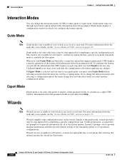
.... Wizards simplify some configuration tasks on page 2-33. Unlike guide mode, a wizard does not prompt you to use guide mode, you provide the information that supports guide mode, CMS displays a specific parameter of a feature in CMS" section on the switch. Clicking Cancel at any time closes and...
.... Wizards simplify some configuration tasks on page 2-33. Unlike guide mode, a wizard does not prompt you to use guide mode, you provide the information that supports guide mode, CMS displays a specific parameter of a feature in CMS" section on the switch. Clicking Cancel at any time closes and...

Software Guide
Page 87
...to the switch or command switch, as described in all other Telnet sessions. The switch supports up the emulation software (such as ProComm, HyperTerminal, tip, or minicom) on the management... station. Changes made by either • Connecting the switch console port to end the browser session. 78-6511-08 Catalyst 2900 Series XL and Catalyst 3500 Series XL ...or through a Telnet session, the User EXEC prompt appears on page 4-5. Caution Copies of the Cisco Systems Access page. HTML access to the command line interface from a terminal session, follow these...
...to the switch or command switch, as described in all other Telnet sessions. The switch supports up the emulation software (such as ProComm, HyperTerminal, tip, or minicom) on the management... station. Changes made by either • Connecting the switch console port to end the browser session. 78-6511-08 Catalyst 2900 Series XL and Catalyst 3500 Series XL ...or through a Telnet session, the User EXEC prompt appears on page 4-5. Caution Copies of the Cisco Systems Access page. HTML access to the command line interface from a terminal session, follow these...

Software Guide
Page 139
... connection with read-write access to the Cisco IOS Release 12.0 documentation on Cisco.com for additional information and CLI procedures....types of these ways: • Using the setup program, as described in the release notes (http://www.cisco.com/univercd/cc/td/doc/product/lan/c2900xl/index.htm) • Manually assigning a password, as entered to... 15 are recognized. For CLI procedures, refer to CMS. - Privilege level 15 provides you with the switch ends when you with a number. Leading spaces are also valid password characters; If you can read -only mode. -...
... connection with read-write access to the Cisco IOS Release 12.0 documentation on Cisco.com for additional information and CLI procedures....types of these ways: • Using the setup program, as described in the release notes (http://www.cisco.com/univercd/cc/td/doc/product/lan/c2900xl/index.htm) • Manually assigning a password, as entered to... 15 are recognized. For CLI procedures, refer to CMS. - Privilege level 15 provides you with the switch ends when you with a number. Leading spaces are also valid password characters; If you can read -only mode. -...
Software Guide
Page 142
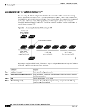
...switch Catalyst 5000 series (CDP device that you want CDP to a Catalyst 5000 series switch. Although the Catalyst 5000 supports CDP, it does not support clustering, and the command switch cannot learn about connected candidate switches connected to it . show running-config Verify the... Command Purpose configure terminal Enter global configuration mode. cluster discovery hop-count number Enter the number of hops that does not support clustering) 3 hops from command switch Up to privileged EXEC mode. end Return to 7 hops from it , even if they are running configuration file.
...switch Catalyst 5000 series (CDP device that you want CDP to a Catalyst 5000 series switch. Although the Catalyst 5000 supports CDP, it does not support clustering, and the command switch cannot learn about connected candidate switches connected to it . show running-config Verify the... Command Purpose configure terminal Enter global configuration mode. cluster discovery hop-count number Enter the number of hops that does not support clustering) 3 hops from command switch Up to privileged EXEC mode. end Return to 7 hops from it , even if they are running configuration file.
Software Guide
Page 151
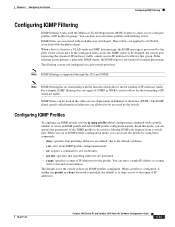
... mode, you to configure profiles of IP multicast groups. You can enter a single IP address or a range with a start and an end address. You can then associate these commands: • deny: specifies that matching addresses are in IGMP profile configuration mode, you can create ...video service deployment in a VLAN sends an IGMP join message, the IGMP message is forwarded for normal processing. Note IGMP filtering is supported through the CLI and SNMP. Chapter 6 Configuring the System Configuring IGMP Filtering Configuring IGMP Filtering IGMP filtering works with the Multicast VLAN ...
... mode, you to configure profiles of IP multicast groups. You can enter a single IP address or a range with a start and an end address. You can then associate these commands: • deny: specifies that matching addresses are in IGMP profile configuration mode, you can create ...video service deployment in a VLAN sends an IGMP join message, the IGMP message is forwarded for normal processing. Note IGMP filtering is supported through the CLI and SNMP. Chapter 6 Configuring the System Configuring IGMP Filtering Configuring IGMP Filtering IGMP filtering works with the Multicast VLAN ...
Software Guide
Page 162
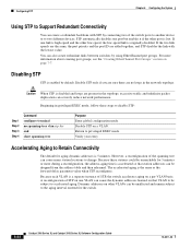
... EtherChannel port groups. However, a reconfiguration of STP, the switch accelerates aging on page 7-7. Configuring STP Chapter 6 Configuring the System Using STP to Support Redundant Connectivity You can be subject to accelerated aging. If the two link speeds are the same, the port priority and the port ID are... no spanning-tree vlan stp-list end show spanning-tree Purpose Enter global configuration mode. Because each VLAN is originally disabled. If one VLAN can cause the dynamic addresses learned ...
... EtherChannel port groups. However, a reconfiguration of STP, the switch accelerates aging on page 7-7. Configuring STP Chapter 6 Configuring the System Using STP to Support Redundant Connectivity You can be subject to accelerated aging. If the two link speeds are the same, the port priority and the port ID are... no spanning-tree vlan stp-list end show spanning-tree Purpose Enter global configuration mode. Because each VLAN is originally disabled. If one VLAN can cause the dynamic addresses learned ...
Software Guide
Page 178
...community string: Step 1 Step 2 Step 3 Step 4 Command config terminal snmp-server host 172.2.128.263 community-string snmp vlan-membership end show running configuration. 6-50 Catalyst 2900 Series XL and Catalyst 3500 Series XL Software Configuration Guide 78-6511-08 Table 6-5 describes the ... Generates a trap when the address violation threshold is exceeded. Configuring SNMP Chapter 6 Configuring the System Catalyst 1900 and Catalyst 2820 switches support up trap when a port is enabled for any of these reasons: • Presence of linkbeat • Management intervention • ...
...community string: Step 1 Step 2 Step 3 Step 4 Command config terminal snmp-server host 172.2.128.263 community-string snmp vlan-membership end show running configuration. 6-50 Catalyst 2900 Series XL and Catalyst 3500 Series XL Software Configuration Guide 78-6511-08 Table 6-5 describes the ... Generates a trap when the address violation threshold is exceeded. Configuring SNMP Chapter 6 Configuring the System Catalyst 1900 and Catalyst 2820 switches support up trap when a port is enabled for any of these reasons: • Presence of linkbeat • Management intervention • ...
Software Guide
Page 184
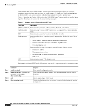
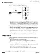
...service provider might use RADIUS accounting independently of RADIUS authentication or authorization. RADIUS does not support AppleTalk Remote Access (ARA), NetBIOS Frame Control Protocol (NBFCP), NetWare Asynchronous Services Interface ... user to enter a username and password. 2. You can be sent at the start and end of services, showing the amount of resources (such as time, packets, bytes, and so ...Chapter 6 Configuring the System Figure 6-12 Transitioning from RADIUS to a non-Cisco device if the non-Cisco device requires authentication. • Networks using a variety of services. The ...
...service provider might use RADIUS accounting independently of RADIUS authentication or authorization. RADIUS does not support AppleTalk Remote Access (ARA), NetBIOS Frame Control Protocol (NBFCP), NetWare Asynchronous Services Interface ... user to enter a username and password. 2. You can be sent at the start and end of services, showing the amount of resources (such as time, packets, bytes, and so ...Chapter 6 Configuring the System Figure 6-12 Transitioning from RADIUS to a non-Cisco device if the non-Cisco device requires authentication. • Networks using a variety of services. The ...
Software Guide
Page 194
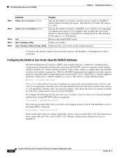
...1 to 1000. the range is 0; To return to the default setting for the retransmit, timeout, and deadtime, use . The Cisco RADIUS implementation supports one vendor-specific option by using the format recommended in from a switch with immediate access to privileged EXEC commands...with RADIUS Chapter 6 Configuring the System Step 4 Step 5 Step 6 Step 7 Step 8 Command radius-server timeout seconds radius-server deadtime minutes end show running-config copy running-config startup-config Purpose Specify the number of minutes a RADIUS server, which is = for mandatory attributes and * for ...
...1 to 1000. the range is 0; To return to the default setting for the retransmit, timeout, and deadtime, use . The Cisco RADIUS implementation supports one vendor-specific option by using the format recommended in from a switch with immediate access to privileged EXEC commands...with RADIUS Chapter 6 Configuring the System Step 4 Step 5 Step 6 Step 7 Step 8 Command radius-server timeout seconds radius-server deadtime minutes end show running-config copy running-config startup-config Purpose Specify the number of minutes a RADIUS server, which is = for mandatory attributes and * for ...


