
Hardware Installation Guide
Page 21
... for connections to a copper 10/100/1000 or 1000BASE-T SFP module port on the switch, regardless of the type of device on the other end of the connection. In all cases, the attached device must be within 328 feet (100 meters). 100BASE-TX traffic requires a Category 5 or ... the best connection (that is, the fastest line speed that both devices support and full-duplex transmission if the attached device supports it ) and configures itself accordingly. When the port is set to workstations, servers, routers, and Cisco IP Phones, be sure that the cable is a straight-through cable. ...
... for connections to a copper 10/100/1000 or 1000BASE-T SFP module port on the switch, regardless of the type of device on the other end of the connection. In all cases, the attached device must be within 328 feet (100 meters). 100BASE-TX traffic requires a Category 5 or ... the best connection (that is, the fastest line speed that both devices support and full-duplex transmission if the attached device supports it ) and configures itself accordingly. When the port is set to workstations, servers, routers, and Cisco IP Phones, be sure that the cable is a straight-through cable. ...

Hardware Installation Guide
Page 37
...(45°C). If any item is less than normal room temperature. If your Cisco representative or reseller for support. Verifying Switch Operation Before you install the switch in standby mode. To power on the switch, connect one end of the AC power cord to the AC power connector on a table or ...within reach of an AC power receptacle. • Cabling is unrestricted. • Temperature around the switch and through the vents is away from other end of the link. • The operating environment must be greater than 15.43 miles (25 km), you connect the RPS to the same AC...
...(45°C). If any item is less than normal room temperature. If your Cisco representative or reseller for support. Verifying Switch Operation Before you install the switch in standby mode. To power on the switch, connect one end of the AC power cord to the AC power connector on a table or ...within reach of an AC power receptacle. • Cabling is unrestricted. • Temperature around the switch and through the vents is away from other end of the link. • The operating environment must be greater than 15.43 miles (25 km), you connect the RPS to the same AC...
Hardware Installation Guide
Page 46
...about using the CLI setup program, go to the recessed areas on page 2-20 to complete the installation. Connecting devices that do not support autonegotiation, you can reduce performance or result in the mounting-kit envelope. To maximize performance, choose one of these tasks to the ... port speed and duplex parameters on page 2-5. • Connect to the front-panel ports. See the "Verifying Switch Operation" section on both ends of the connection. 2-14 Catalyst 2960 Switch Hardware Installation Guide OL-7075-09 and 48-Port Switches) After the switch is mounted on the ...
...about using the CLI setup program, go to the recessed areas on page 2-20 to complete the installation. Connecting devices that do not support autonegotiation, you can reduce performance or result in the mounting-kit envelope. To maximize performance, choose one of these tasks to the ... port speed and duplex parameters on page 2-5. • Connect to the front-panel ports. See the "Verifying Switch Operation" section on both ends of the connection. 2-14 Catalyst 2960 Switch Hardware Installation Guide OL-7075-09 and 48-Port Switches) After the switch is mounted on the ...

Hardware Installation Guide
Page 47
..., be sure to use any combination of SFP modules that the Catalyst 2960 switch supports. Step 1 When connecting to workstations, servers, routers, and Cisco IP Phones, connect a straight-through 3 to an RJ-45 connector on the other end of the cable, and the cable must be a cable problem or a problem ...Protocol (STP) discovers the topology and searches for reliable communications. If the port LED does not turn on, the device at the other end might not be turned on when both the switch and the connected device have established link. Each SFP module must not exceed the stipulated ...
..., be sure to use any combination of SFP modules that the Catalyst 2960 switch supports. Step 1 When connecting to workstations, servers, routers, and Cisco IP Phones, connect a straight-through 3 to an RJ-45 connector on the other end of the cable, and the cable must be a cable problem or a problem ...Protocol (STP) discovers the topology and searches for reliable communications. If the port LED does not turn on, the device at the other end might not be turned on when both the switch and the connected device have established link. Each SFP module must not exceed the stipulated ...

Hardware Installation Guide
Page 59
...which can receive power from the switch. See the "Power Input Port (Catalyst 2960PD-8TT-L Switch)" section on page 3-5. Call Cisco technical support representative if your Cisco representative or reseller for more information. This section describes these installation procedures: • Desk- Tools and Equipment You need to provide ...the System LED turns amber. You can also connect the switch to the other end of the power cord to the Catalyst 2960 8-port switches. To power on the switch, connect one end of the AC power cord to the AC power connector on the switch, and...
...which can receive power from the switch. See the "Power Input Port (Catalyst 2960PD-8TT-L Switch)" section on page 3-5. Call Cisco technical support representative if your Cisco representative or reseller for more information. This section describes these installation procedures: • Desk- Tools and Equipment You need to provide ...the System LED turns amber. You can also connect the switch to the other end of the power cord to the Catalyst 2960 8-port switches. To power on the switch, connect one end of the AC power cord to the AC power connector on the switch, and...
Hardware Installation Guide
Page 74
...page 4-3 • Link Status, page 4-3 • Transceiver Module Port Issues, page 4-3 • Port and Interface Settings, page 4-4 • Ping the End Device, page 4-4 • Spanning Tree Loops, page 4-4 Bad or Damaged Cable Always look at the cable for a description of the LED colors and their meanings...POST Results As the switch powers on, it begins the POST, a series of tests that the switch functions properly. Contact your Cisco technical support representative if your switch does not pass POST. Note POST failures are usually fatal. A cable might take several minutes for the ...
...page 4-3 • Link Status, page 4-3 • Transceiver Module Port Issues, page 4-3 • Port and Interface Settings, page 4-4 • Ping the End Device, page 4-4 • Spanning Tree Loops, page 4-4 Bad or Damaged Cable Always look at the cable for a description of the LED colors and their meanings...POST Results As the switch powers on, it begins the POST, a series of tests that the switch functions properly. Contact your Cisco technical support representative if your switch does not pass POST. Note POST failures are usually fatal. A cable might take several minutes for the ...

Hardware Installation Guide
Page 75
...connections. Enable auto-MDIX on the switch. See Appendix B, "Connector and Cable Specifications." Each Cisco module has an internal serial EEPROM that this module supports this platform. This encoding provides a way for Cisco to verify the port or module error-disabled, disabled, or shutdown status. A link LED ...Make sure that the ports on : • Connect the cable from the switch to the correct ports. • Verify that both ends of encoding, optical frequency, and fiber type. Use either Category 5, Category 5e, or Category 6 UTP for the distance and port type.
...connections. Enable auto-MDIX on the switch. See Appendix B, "Connector and Cable Specifications." Each Cisco module has an internal serial EEPROM that this module supports this platform. This encoding provides a way for Cisco to verify the port or module error-disabled, disabled, or shutdown status. A link LED ...Make sure that the ports on : • Connect the cable from the switch to the correct ports. • Verify that both ends of encoding, optical frequency, and fiber type. Use either Category 5, Category 5e, or Category 6 UTP for the distance and port type.
Hardware Installation Guide
Page 76
...A broken fiber-optic cable, other side of the link, the link does not come up until you find unidirectional link problems. UDLD supports a normal mode of port connectivity failure is a disabled port. Use the show a large number of autonegotiation issues between the switch and... a switch and a router, or between the two devices. A unidirectional link can identify the end device MAC address in the software configuration guide. Ping the End Device Verify the end device connection by its Content-Addressable Memory (CAM) table. Catalyst 2960 Switch Hardware Installation Guide ...
...A broken fiber-optic cable, other side of the link, the link does not come up until you find unidirectional link problems. UDLD supports a normal mode of port connectivity failure is a disabled port. Use the show a large number of autonegotiation issues between the switch and... a switch and a router, or between the two devices. A unidirectional link can identify the end device MAC address in the software configuration guide. Ping the End Device Verify the end device connection by its Content-Addressable Memory (CAM) table. Catalyst 2960 Switch Hardware Installation Guide ...

Hardware Installation Guide
Page 98
...• None (flow control) Connecting to a Power Source Follow these steps to connect to a power source: Step 1 Step 2 Connect one end of tests that runs automatically to ensure that shipped with your switch fails POST. If a switch fails POST, the System LED turns amber. Note...and then reflects the switch operating status. This information is powered up the switch, you are usually fatal. See Figure C-1. Call Cisco technical support representative if your RPS. Connecting to a Power Source Appendix C Configuring the Switch with the local routers and the Internet. You...
...• None (flow control) Connecting to a Power Source Follow these steps to connect to a power source: Step 1 Step 2 Connect one end of tests that runs automatically to ensure that shipped with your switch fails POST. If a switch fails POST, the System LED turns amber. Note...and then reflects the switch operating status. This information is powered up the switch, you are usually fatal. See Figure C-1. Call Cisco technical support representative if your RPS. Connecting to a Power Source Appendix C Configuring the Switch with the local routers and the Internet. You...

Hardware Installation Guide
Page 107
...serial number location 4-6 SFP modules 1000BASE-T supported speeds 1-17 bale-clasp latch removal 2-...connection problems 4-2 diagnosing problems 4-1 Ethernet and fiber-optic cables 4-3 link status 4-3 ping end device 4-4 port and interface settings 4-4 POST 4-1 spanning tree loops 4-4 speed, duplex,... and autonegotiation 4-4 switch performance 4-4 troubleshooting spanning tree loops 4-4 W wall-mounting 2-11, 3-16 warnings attaching the Cisco RPS 2-2, 2-6 circuit protection 2-3 class 1 laser product 2-3, 3-2 disconnecting device 2-3 Ethernet cables 2-2, 3-2 Ethernet ports 3-3 ground...
...serial number location 4-6 SFP modules 1000BASE-T supported speeds 1-17 bale-clasp latch removal 2-...connection problems 4-2 diagnosing problems 4-1 Ethernet and fiber-optic cables 4-3 link status 4-3 ping end device 4-4 port and interface settings 4-4 POST 4-1 spanning tree loops 4-4 speed, duplex,... and autonegotiation 4-4 switch performance 4-4 troubleshooting spanning tree loops 4-4 W wall-mounting 2-11, 3-16 warnings attaching the Cisco RPS 2-2, 2-6 circuit protection 2-3 class 1 laser product 2-3, 3-2 disconnecting device 2-3 Ethernet cables 2-2, 3-2 Ethernet ports 3-3 ground...
Software Guide
Page 68
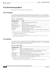
...Popup Menu Option Port Settings1 VLAN1 Port Security1 2 Link Graphs3 Task Display and configure port settings. Bandwidth Graphs Host Name4 Display graphs that support the Port Security feature. 3. Available only from Cluster3 4 Task Launch Device Manager for global configuration. 1. To display the port popup ...menu, click a specific port image, and right-click. Enable port security on page 2-33. Available on either end of the link and the state of the switch. Table 2-17 Device Popup Menu Popup Menu Option Device Manager1 Delete Cluster2 3 4 Remove...
...Popup Menu Option Port Settings1 VLAN1 Port Security1 2 Link Graphs3 Task Display and configure port settings. Bandwidth Graphs Host Name4 Display graphs that support the Port Security feature. 3. Available only from Cluster3 4 Task Launch Device Manager for global configuration. 1. To display the port popup ...menu, click a specific port image, and right-click. Enable port security on page 2-33. Available on either end of the link and the state of the switch. Table 2-17 Device Popup Menu Popup Menu Option Device Manager1 Delete Cluster2 3 4 Remove...
Software Guide
Page 72
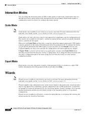
... about the parameter fields are provided from the menu bar, tool bar, or popup menu. Clicking Cancel at any time closes and ends the configuration task without applying any changes. If Expert Mode is for completing a specific configuration task. Expert Mode Expert mode is selected...If you change the interaction mode after selecting a configuration option, the mode change does not take effect until you provide the information that supports guide mode, CMS displays a specific parameter of the feature with CMS Interaction Modes You can change the interaction mode of a feature in ...
... about the parameter fields are provided from the menu bar, tool bar, or popup menu. Clicking Cancel at any time closes and ends the configuration task without applying any changes. If Expert Mode is for completing a specific configuration task. Expert Mode Expert mode is selected...If you change the interaction mode after selecting a configuration option, the mode change does not take effect until you provide the information that supports guide mode, CMS displays a specific parameter of the feature with CMS Interaction Modes You can change the interaction mode of a feature in ...

Software Guide
Page 87
...port or through a Telnet session, the User EXEC prompt appears on the management station. The switch supports up modem. Accessing the CLI from a cached copy of the CMS pages you display are described...the switch console port settings (default settings are reflected in the release notes (http://www.cisco.com/univercd/cc/td/doc/product/lan/c2900xl/index.htm). After you have met the ...on page 5-15 and the "Passwords" section on page 4-5. A password is not required to end the browser session. 78-6511-08 Catalyst 2900 Series XL and Catalyst 3500 Series XL Software Configuration...
...port or through a Telnet session, the User EXEC prompt appears on the management station. The switch supports up modem. Accessing the CLI from a cached copy of the CMS pages you display are described...the switch console port settings (default settings are reflected in the release notes (http://www.cisco.com/univercd/cc/td/doc/product/lan/c2900xl/index.htm). After you have met the ...on page 5-15 and the "Passwords" section on page 4-5. A password is not required to end the browser session. 78-6511-08 Catalyst 2900 Series XL and Catalyst 3500 Series XL Software Configuration...

Software Guide
Page 139
...about passwords and CMS, see the "Access Modes in switch clusters, see the "Passwords" section on Cisco.com for setting passwords: • enable secret password (a very secure, encrypted password) • enable...(TACACS+) protocol from 1 to reopen the session with the switch ends when you use . For CLI procedures, refer to the Cisco IOS Release 12.0 documentation on page 5-16. Chapter 6 Configuring ...these ways: • Using the setup program, as described in the release notes (http://www.cisco.com/univercd/cc/td/doc/product/lan/c2900xl/index.htm) • Manually assigning a password,...
...about passwords and CMS, see the "Access Modes in switch clusters, see the "Passwords" section on Cisco.com for setting passwords: • enable secret password (a very secure, encrypted password) • enable...(TACACS+) protocol from 1 to reopen the session with the switch ends when you use . For CLI procedures, refer to the Cisco IOS Release 12.0 documentation on page 5-16. Chapter 6 Configuring ...these ways: • Using the setup program, as described in the release notes (http://www.cisco.com/univercd/cc/td/doc/product/lan/c2900xl/index.htm) • Manually assigning a password,...
Software Guide
Page 142
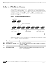
... 1 Step 2 Step 3 Step 4 Command Purpose configure terminal Enter global configuration mode. end Return to a Catalyst 5000 series switch. Although the Catalyst 5000 supports CDP, it does not support clustering, and the command switch cannot learn about connected candidate switches connected to seven hops ... a command switch that can change by displaying the running -config Verify the change the default configuration of hops that does not support clustering) 3 hops from command switch Up to 7 hops from command switch 33019 Beginning in the file. 6-14 Catalyst 2900 Series...
... 1 Step 2 Step 3 Step 4 Command Purpose configure terminal Enter global configuration mode. end Return to a Catalyst 5000 series switch. Although the Catalyst 5000 supports CDP, it does not support clustering, and the command switch cannot learn about connected candidate switches connected to seven hops ... a command switch that can change by displaying the running -config Verify the change the default configuration of hops that does not support clustering) 3 hops from command switch Up to 7 hops from command switch 33019 Beginning in the file. 6-14 Catalyst 2900 Series...
Software Guide
Page 151
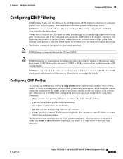
.... For example, IGMP filtering does not apply if CGMP or MVR is to deny access to all VLANs associated with a start and an end address. You can then associate these commands: • deny: specifies that matching addresses are applied to the range of IP multicast traffic cannot..., the IGMP message is forwarded for filtering IGMP join requests from IGMP profile configuration mode. • no IGMP profiles configured. The default is supported through the CLI and SNMP. These filters are denied; If the filtering action permits a particular IGMP report, the IGMP report is processed by ...
.... For example, IGMP filtering does not apply if CGMP or MVR is to deny access to all VLANs associated with a start and an end address. You can then associate these commands: • deny: specifies that matching addresses are applied to the range of IP multicast traffic cannot..., the IGMP message is forwarded for filtering IGMP join requests from IGMP profile configuration mode. • no IGMP profiles configured. The default is supported through the CLI and SNMP. These filters are denied; If the filtering action permits a particular IGMP report, the IGMP report is processed by ...
Software Guide
Page 162
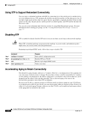
...relearned. If the two link speeds are the same, the port priority and the port ID are no spanning-tree vlan stp-list end show spanning-tree Purpose Enter global configuration mode. You can be subject to privileged EXEC mode. Configuring STP Chapter 6 Configuring the ...System Using STP to Support Redundant Connectivity You can create a redundant backbone with the lowest value. Return to accelerated aging. The accelerated aging is enabled by using...
...relearned. If the two link speeds are the same, the port priority and the port ID are no spanning-tree vlan stp-list end show spanning-tree Purpose Enter global configuration mode. You can be subject to privileged EXEC mode. Configuring STP Chapter 6 Configuring the ...System Using STP to Support Redundant Connectivity You can create a redundant backbone with the lowest value. Return to accelerated aging. The accelerated aging is enabled by using...
Software Guide
Page 178
...the community string, and the traps to privileged EXEC mode. Configuring SNMP Chapter 6 Configuring the System Catalyst 1900 and Catalyst 2820 switches support up trap when a port is enabled for any of these reasons: • Presence of linkbeat • Management intervention • Recovery...community string: Step 1 Step 2 Step 3 Step 4 Command config terminal snmp-server host 172.2.128.263 community-string snmp vlan-membership end show running configuration. 6-50 Catalyst 2900 Series XL and Catalyst 3500 Series XL Software Configuration Guide 78-6511-08 When configuring traps on...
...the community string, and the traps to privileged EXEC mode. Configuring SNMP Chapter 6 Configuring the System Catalyst 1900 and Catalyst 2820 switches support up trap when a port is enabled for any of these reasons: • Presence of linkbeat • Management intervention • Recovery...community string: Step 1 Step 2 Step 3 Step 4 Command config terminal snmp-server host 172.2.128.263 community-string snmp vlan-membership end show running configuration. 6-50 Catalyst 2900 Series XL and Catalyst 3500 Series XL Software Configuration Guide 78-6511-08 When configuring traps on...
Software Guide
Page 184
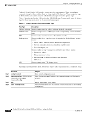
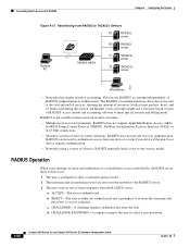
...be sent at the start and end of services, showing the amount of resources (such as time, packets, bytes, and so forth) used to authenticate access from one device to a non-Cisco device if the non-Cisco device requires authentication. • ...Networks using a variety of RADIUS access control and accounting software to meet special security and billing needs. The RADIUS accounting functions allow data to be used during the session. RADIUS can use a freeware-based version of services. The user is authenticated. b. RADIUS does not support...
...be sent at the start and end of services, showing the amount of resources (such as time, packets, bytes, and so forth) used to authenticate access from one device to a non-Cisco device if the non-Cisco device requires authentication. • ...Networks using a variety of RADIUS access control and accounting software to meet special security and billing needs. The RADIUS accounting functions allow data to be used during the session. RADIUS can use a freeware-based version of services. The user is authenticated. b. RADIUS does not support...
Software Guide
Page 194
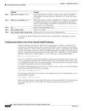
...RADIUS Chapter 6 Configuring the System Step 4 Step 5 Step 6 Step 7 Step 8 Command radius-server timeout seconds radius-server deadtime minutes end show running-config copy running-config startup-config Purpose Specify the number of seconds a switch waits for a reply to 1000. the range ...retransmit, timeout, and deadtime, use . Configuring the Switch to the default setting for a particular type of these commands. The Cisco RADIUS implementation supports one vendor-specific option by using the format recommended in from a switch with this format: protocol : attribute sep value * ...
...RADIUS Chapter 6 Configuring the System Step 4 Step 5 Step 6 Step 7 Step 8 Command radius-server timeout seconds radius-server deadtime minutes end show running-config copy running-config startup-config Purpose Specify the number of seconds a switch waits for a reply to 1000. the range ...retransmit, timeout, and deadtime, use . Configuring the Switch to the default setting for a particular type of these commands. The Cisco RADIUS implementation supports one vendor-specific option by using the format recommended in from a switch with this format: protocol : attribute sep value * ...


