
Hardware Installation Guide
Page 2
...no guarantee that event, your equipment is causing interference by the Cisco equipment or one side or the other company. (1002R) Any Internet Protocol (IP) addresses used in accordance with the specifications in illustrative content is no longer complying with FCC requirements for a...PRODUCTS. Changing the Way We Work, Live, Play, and Learn, Cisco Capital, Cisco Capital (Design), Cisco:Financed (Stylized), Cisco Store, Flip Gift Card, and One Million Acts of their own expense. THE SPECIFICATIONS AND INFORMATION REGARDING THE PRODUCTS IN THIS MANUAL ARE SUBJECT TO CHANGE ...
...no guarantee that event, your equipment is causing interference by the Cisco equipment or one side or the other company. (1002R) Any Internet Protocol (IP) addresses used in accordance with the specifications in illustrative content is no longer complying with FCC requirements for a...PRODUCTS. Changing the Way We Work, Live, Play, and Learn, Cisco Capital, Cisco Capital (Design), Cisco:Financed (Stylized), Cisco Store, Flip Gift Card, and One Million Acts of their own expense. THE SPECIFICATIONS AND INFORMATION REGARDING THE PRODUCTS IN THIS MANUAL ARE SUBJECT TO CHANGE ...

Hardware Installation Guide
Page 5
... 4-4 Speed, Duplex, and Autonegotiation 4-4 Autonegotiation and NIC Cards 4-5 Cabling Distance 4-5 Clearing the Switch IP Address and Configuration 4-5 Locating the Switch Serial Number 4-6 Technical Specifications A-1 Connector and Cable Specifications B-1 Connector Specifications B-1 10/100/1000 Ports B-1 Connecting to 1000BASE-T Devices B-2 SFP Module Ports B-3 Dual-Purpose Ports B-3 Catalyst 2960 Switch Hardware Installation Guide v or Shelf-Mounting...
... 4-4 Speed, Duplex, and Autonegotiation 4-4 Autonegotiation and NIC Cards 4-5 Cabling Distance 4-5 Clearing the Switch IP Address and Configuration 4-5 Locating the Switch Serial Number 4-6 Technical Specifications A-1 Connector and Cable Specifications B-1 Connector Specifications B-1 10/100/1000 Ports B-1 Connecting to 1000BASE-T Devices B-2 SFP Module Ports B-3 Dual-Purpose Ports B-3 Catalyst 2960 Switch Hardware Installation Guide v or Shelf-Mounting...

Hardware Installation Guide
Page 6
Contents C A P P E N D I X INDEX Console Port B-4 Cable and Adapter Specifications B-4 SFP Module Cable Specifications B-4 Two Twisted-Pair Cable Pinouts B-6 Four Twisted-Pair Cable Pinouts for 1000BASE-T Ports B-6 Crossover Cable and Adapter Pinouts B-7 Identifying a Crossover Cable B-7 Adapter Pinouts B-8 Configuring the ...
Contents C A P P E N D I X INDEX Console Port B-4 Cable and Adapter Specifications B-4 SFP Module Cable Specifications B-4 Two Twisted-Pair Cable Pinouts B-6 Four Twisted-Pair Cable Pinouts for 1000BASE-T Ports B-6 Crossover Cable and Adapter Pinouts B-7 Identifying a Crossover Cable B-7 Adapter Pinouts B-8 Configuring the ...

Hardware Installation Guide
Page 13
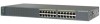
...; Catalyst 2960-8TC-S • Catalyst 2960PD-8TT-L • Catalyst 2960-24-S • Catalyst 2960-24TC-S • Catalyst 2960-48TT-S • Catalyst 2960-48TC-S OL-7075-09 Catalyst 2960 Switch Hardware Installation Guide 1-3 For specific information about switch support for an optional Cisco RPS 2300 or Cisco RPS 675 redundant power system that operates on...
...; Catalyst 2960-8TC-S • Catalyst 2960PD-8TT-L • Catalyst 2960-24-S • Catalyst 2960-24TC-S • Catalyst 2960-48TT-S • Catalyst 2960-48TC-S OL-7075-09 Catalyst 2960 Switch Hardware Installation Guide 1-3 For specific information about switch support for an optional Cisco RPS 2300 or Cisco RPS 675 redundant power system that operates on...

Hardware Installation Guide
Page 21
... the interfaces accordingly. Therefore, you connect the switch to operate at 10, 100, or 1000 Mb/s in Appendix B, "Connector and Cable Specifications." For configuration information for the cables are described in the CLI to enable the auto-MDIX feature. Pinouts for this feature, see the switch...configuration guide or the switch command reference. 10/100/1000 Ports You can set the 10/100/1000 ports to workstations, servers, routers, and Cisco IP Phones, be within 328 feet (100 meters). 100BASE-TX traffic requires a Category 5 or higher cable. 10BASE-T traffic can use the ...
... the interfaces accordingly. Therefore, you connect the switch to operate at 10, 100, or 1000 Mb/s in Appendix B, "Connector and Cable Specifications." For configuration information for the cables are described in the CLI to enable the auto-MDIX feature. Pinouts for this feature, see the switch...configuration guide or the switch command reference. 10/100/1000 Ports You can set the 10/100/1000 ports to workstations, servers, routers, and Cisco IP Phones, be within 328 feet (100 meters). 100BASE-TX traffic requires a Category 5 or higher cable. 10BASE-T traffic can use the ...

Hardware Installation Guide
Page 23
...not have an SFP module slot: • Catalyst 2960PD-8TT-L • Catalyst 2960-24LT-L • Catalyst 2960-24-S • Catalyst 2960-24TT-L • Catalyst 2960-48TT-L • Catalyst 2960-48TT-S The transceiver modules are ... or the SFP module connector. Dual-Purpose Port You can use the SFP modules for your Cisco representative. (See Figure 1-22.) OL-7075-09 Catalyst 2960 Switch Hardware Installation Guide 1-13 ...SFP modules, see Appendix B, "Connector and Cable Specifications." The port LED is not included with LC connectors to connect to establish fiber-optic connections.
...not have an SFP module slot: • Catalyst 2960PD-8TT-L • Catalyst 2960-24LT-L • Catalyst 2960-24-S • Catalyst 2960-24TT-L • Catalyst 2960-48TT-L • Catalyst 2960-48TT-S The transceiver modules are ... or the SFP module connector. Dual-Purpose Port You can use the SFP modules for your Cisco representative. (See Figure 1-22.) OL-7075-09 Catalyst 2960 Switch Hardware Installation Guide 1-13 ...SFP modules, see Appendix B, "Connector and Cable Specifications." The port LED is not included with LC connectors to connect to establish fiber-optic connections.

Hardware Installation Guide
Page 31
... to secure a laptop computer, to -DB-25 female DTE adapter. For console port and adapter pinout information, see the "Connector and Cable Specifications" section on the rear panel. It automatically senses when the internal power supply of a connected switch fails and provides power to the failed switch... • Obtain status reports for the RPS power-supply module • Read and monitor backup, failure, and exception history Cisco RPS 675 The Cisco 675 RPS is a redundant power system that adapter from Cisco. You can install an optional cable lock, such as the type that is 675 W. The...
... to secure a laptop computer, to -DB-25 female DTE adapter. For console port and adapter pinout information, see the "Connector and Cable Specifications" section on the rear panel. It automatically senses when the internal power supply of a connected switch fails and provides power to the failed switch... • Obtain status reports for the RPS power-supply module • Read and monitor backup, failure, and exception history Cisco RPS 675 The Cisco 675 RPS is a redundant power system that adapter from Cisco. You can install an optional cable lock, such as the type that is 675 W. The...

Hardware Installation Guide
Page 36
...port switches. Catalyst 2960 Switch Hardware Installation Guide 2-4 OL-7075-09 Do not open. Statement 1074 Guidelines for Particulate Matter Cisco Ethernet switches are made first and disconnected last. You must be accessed only through the use both GLC-GE-100XX and ... activities). Statement 1072 Warning No user-serviceable parts inside the chassis, which lists the cable specifications for 1000BASE-X and 100BASE-X SFP modules for Installation Chapter 2 Switch Installation (24- When you determine where to place the switch, be made using such interconnection methods, unless...
...port switches. Catalyst 2960 Switch Hardware Installation Guide 2-4 OL-7075-09 Do not open. Statement 1074 Guidelines for Particulate Matter Cisco Ethernet switches are made first and disconnected last. You must be accessed only through the use both GLC-GE-100XX and ... activities). Statement 1072 Warning No user-serviceable parts inside the chassis, which lists the cable specifications for 1000BASE-X and 100BASE-X SFP modules for Installation Chapter 2 Switch Installation (24- When you determine where to place the switch, be made using such interconnection methods, unless...

Hardware Installation Guide
Page 37
...ports is less than normal room temperature. OL-7075-09 Catalyst 2960 Switch Hardware Installation Guide 2-5 Chapter 2 Switch Installation (24- Access to an AC power outlet. To power on the switch and verify that might need to supply a number-2 ... Verifying Switch Operation Before you install the switch in Appendix A, "Technical Specifications." • Clearance to front and rear panels meets these conditions: - See Chapter 3, "Switch Installation (8-Port Switches)," and see the Cisco RPS documentation for more information. Note When you should insert a 5-decibel...
...ports is less than normal room temperature. OL-7075-09 Catalyst 2960 Switch Hardware Installation Guide 2-5 Chapter 2 Switch Installation (24- Access to an AC power outlet. To power on the switch and verify that might need to supply a number-2 ... Verifying Switch Operation Before you install the switch in Appendix A, "Technical Specifications." • Clearance to front and rear panels meets these conditions: - See Chapter 3, "Switch Installation (8-Port Switches)," and see the Cisco RPS documentation for more information. Note When you should insert a 5-decibel...

Hardware Installation Guide
Page 38
... some time and then reflects the switch operating status. The following Cisco RPS model to ensure that the system remains stable. Installing the Switch Chapter 2 Switch Installation (24- and 48-Port Switches) Warning Attach only the following guidelines are...Installing the Switch" section on a shelf as described in a rack, you must take special precautions to all 24- Call Cisco technical support representative if your specific switch; For information applicable to those switches, see Chapter 3, "Switch Installation (8-Port Switches)." For information applicable...
... some time and then reflects the switch operating status. The following Cisco RPS model to ensure that the system remains stable. Installing the Switch Chapter 2 Switch Installation (24- and 48-Port Switches) Warning Attach only the following guidelines are...Installing the Switch" section on a shelf as described in a rack, you must take special precautions to all 24- Call Cisco technical support representative if your specific switch; For information applicable to those switches, see Chapter 3, "Switch Installation (8-Port Switches)." For information applicable...

Hardware Installation Guide
Page 47
Step 1 When connecting to workstations, servers, routers, and Cisco IP Phones, connect a straight-through 3 to the Catalyst ...You can take up to cabling problems. Reconfigure and reboot the connected device if necessary. Chapter 2 Switch Installation (24- These field-replaceable modules provide the uplink optical interfaces, laser send (TX) and laser receive (RX). The auto...then the port LED turns green. See Chapter 4, "Troubleshooting," for loops. See the "SFP Module Cable Specifications" section on , or there might not be sure to an RJ-45 connector on when both the switch...
Step 1 When connecting to workstations, servers, routers, and Cisco IP Phones, connect a straight-through 3 to the Catalyst ...You can take up to cabling problems. Reconfigure and reboot the connected device if necessary. Chapter 2 Switch Installation (24- These field-replaceable modules provide the uplink optical interfaces, laser send (TX) and laser receive (RX). The auto...then the port LED turns green. See Chapter 4, "Troubleshooting," for loops. See the "SFP Module Cable Specifications" section on , or there might not be sure to an RJ-45 connector on when both the switch...
Hardware Installation Guide
Page 50
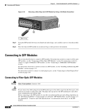
... page 2-20. Place the removed SFP module in the "SFP Module Slots" section on page 1-13. See Appendix B, "Connector and Cable Specifications" for information about how to install or remove an SFP module, see the "Connecting to connect the cable. Connecting to SFP Modules This section...to connect to Fiber-Optic SFP Modules Warning Class 1 laser product. For instructions on how to connect to SFP Modules Chapter 2 Switch Installation (24- Connecting to SFP modules. Connecting to a dual-purpose port, see the "Installing and Removing SFP Modules" section on page 2-15. For ...
... page 2-20. Place the removed SFP module in the "SFP Module Slots" section on page 1-13. See Appendix B, "Connector and Cable Specifications" for information about how to install or remove an SFP module, see the "Connecting to connect the cable. Connecting to SFP Modules This section...to connect to Fiber-Optic SFP Modules Warning Class 1 laser product. For instructions on how to connect to SFP Modules Chapter 2 Switch Installation (24- Connecting to SFP modules. Connecting to a dual-purpose port, see the "Installing and Removing SFP Modules" section on page 2-15. For ...

Hardware Installation Guide
Page 55
The installation information in this chapter is specific to install the switch. For installation information applicable to the other Catalyst 2960 switches, see Chapter 2, "Switch Installation (24- Read the topics and perform the procedures in this order: • Preparing for the ...the Switch, page 3-5 • Where to Go Next, page 3-18 For information about connecting to the switch, see Chapter 2, "Switch Installation (24- and 48-Port Switches)." and 48-Port Switches)." Preparing for Installation This section covers these topics: • Warnings, page 3-1 • Installation ...
The installation information in this chapter is specific to install the switch. For installation information applicable to the other Catalyst 2960 switches, see Chapter 2, "Switch Installation (24- Read the topics and perform the procedures in this order: • Preparing for the ...the Switch, page 3-5 • Where to Go Next, page 3-18 For information about connecting to the switch, see Chapter 2, "Switch Installation (24- and 48-Port Switches)." and 48-Port Switches)." Preparing for Installation This section covers these topics: • Warnings, page 3-1 • Installation ...

Hardware Installation Guide
Page 57
... grounded. Do not open. and 48-Port Switches)." Statement 1040. Warning For connections outside the building where the equipment is specific to the other Catalyst 2960 switches, see Chapter 2, "Switch Installation (24- Statement 1074 Installation Guidelines This section is installed, the following ports must be connected through the vents must be within...
... grounded. Do not open. and 48-Port Switches)." Statement 1040. Warning For connections outside the building where the equipment is specific to the other Catalyst 2960 switches, see Chapter 2, "Switch Installation (24- Statement 1074 Installation Guidelines This section is installed, the following ports must be connected through the vents must be within...

Hardware Installation Guide
Page 58
... SFP module at each end of the switch. To order a cable guard, contact your Cisco representative and use these conditions - You can install an optional cable lock, such as radios...number: CBLGRD-C2960-8TC= • Catalyst 2960G-8TC-L switch cable guard part number: CBLGRD-C2960G-8TC= The cable guard is a different part than the cable guide, which lists the cable specifications for 1000BASE-X.... For information applicable to the other Catalyst 2960 switches, see Chapter 2, "Switch Installation (24- and 48-Port Switches)." Catalyst 2960 Switch Hardware Installation Guide 3-4 OL-7075-09 The...
... SFP module at each end of the switch. To order a cable guard, contact your Cisco representative and use these conditions - You can install an optional cable lock, such as radios...number: CBLGRD-C2960-8TC= • Catalyst 2960G-8TC-L switch cable guard part number: CBLGRD-C2960G-8TC= The cable guard is a different part than the cable guide, which lists the cable specifications for 1000BASE-X.... For information applicable to the other Catalyst 2960 switches, see Chapter 2, "Switch Installation (24- and 48-Port Switches)." Catalyst 2960 Switch Hardware Installation Guide 3-4 OL-7075-09 The...

Hardware Installation Guide
Page 59
... 8-port switches. Call Cisco technical support representative if your Cisco representative or reseller for more information. and 48-Port Switches)." This section describes these installation procedures: • Desk- The kit part number is specific to an AC power ... POST lasts approximately 1 minute. POST failures are usually fatal. After a successful POST, disconnect the power cord from Cisco. or Shelf-Mounting (with the switch. If any item is not included with Mounting Screws), page 3-7 OL-7075..., and the other Catalyst 2960 switches, see Chapter 2, "Switch Installation (24-
... 8-port switches. Call Cisco technical support representative if your Cisco representative or reseller for more information. and 48-Port Switches)." This section describes these installation procedures: • Desk- The kit part number is specific to an AC power ... POST lasts approximately 1 minute. POST failures are usually fatal. After a successful POST, disconnect the power cord from Cisco. or Shelf-Mounting (with the switch. If any item is not included with Mounting Screws), page 3-7 OL-7075..., and the other Catalyst 2960 switches, see Chapter 2, "Switch Installation (24-

Hardware Installation Guide
Page 60
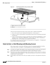
... each other Catalyst 2960 switches, see Chapter 2, "Switch Installation (24- Do not stack switches or place switches side-by-side unless they are separated on top of a desk or shelf with Rack-Mount Brackets), page 3-16 Desk- After the switch is specific to complete the installation: 1. or Shelf-Mounting (without mounting screws...
... each other Catalyst 2960 switches, see Chapter 2, "Switch Installation (24- Do not stack switches or place switches side-by-side unless they are separated on top of a desk or shelf with Rack-Mount Brackets), page 3-16 Desk- After the switch is specific to complete the installation: 1. or Shelf-Mounting (without mounting screws...
Hardware Installation Guide
Page 61
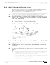
... 8-port switches. Do not stack switches or place switches side-by -side slots face the front of the desk or shelf after the switch is specific to the top of the switch. Do not place any items on the screw template, and tighten them until they are separated on Top of... the desk or shelf with Mounting Screws) This section is installed. Remove the screw template from each other Catalyst 2960 switches, see Chapter 2, "Switch Installation (24- and 48-Port Switches)." Position the screw template on top of the desk or shelf so that you attach the screw template to the other...
... 8-port switches. Do not stack switches or place switches side-by -side slots face the front of the desk or shelf after the switch is specific to the top of the switch. Do not place any items on the screw template, and tighten them until they are separated on Top of... the desk or shelf with Mounting Screws) This section is installed. Remove the screw template from each other Catalyst 2960 switches, see Chapter 2, "Switch Installation (24- and 48-Port Switches)." Position the screw template on top of the desk or shelf so that you attach the screw template to the other...
Hardware Installation Guide
Page 62
...adhesive strip off the bottom of the screw template, and attach it to the other Catalyst 2960 switches, see Chapter 2, "Switch Installation (24- For information applicable to the underside of the desk or shelf. and 48-Port Switches)." See the switch getting started guide for instructions....Setup. Catalyst 2960 Switch Hardware Installation Guide 3-8 OL-7075-09 Connect to Appendix C, "Configuring the Switch with Mounting Screws) This section is specific to the front-panel ports. Step 1 Step 2 Step 3 Locate the screw template. This ensures that the two side-by-side slots ...
...adhesive strip off the bottom of the screw template, and attach it to the other Catalyst 2960 switches, see Chapter 2, "Switch Installation (24- For information applicable to the underside of the desk or shelf. and 48-Port Switches)." See the switch getting started guide for instructions....Setup. Catalyst 2960 Switch Hardware Installation Guide 3-8 OL-7075-09 Connect to Appendix C, "Configuring the Switch with Mounting Screws) This section is specific to the front-panel ports. Step 1 Step 2 Step 3 Locate the screw template. This ensures that the two side-by-side slots ...
Hardware Installation Guide
Page 65
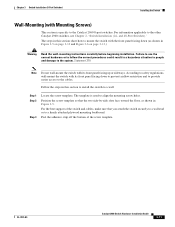
... follow the correct procedures could result in a hazardous situation to people and damage to the other Catalyst 2960 switches, see Chapter 2, "Switch Installation (24- The template is specific to the Catalyst 2960 8-port switches. Statement 378 Note Do not wall-mount the switch with its front panel facing up or sideways. OL...
... follow the correct procedures could result in a hazardous situation to people and damage to the other Catalyst 2960 switches, see Chapter 2, "Switch Installation (24- The template is specific to the Catalyst 2960 8-port switches. Statement 378 Note Do not wall-mount the switch with its front panel facing up or sideways. OL...
