
Hardware Installation Guide
Page 3
... LEDs 1-14 System LED 1-15 RPS LED 1-16 Port LEDs and Modes 1-16 Dual-Purpose Port LEDs 1-18 Cable Guard for the Catalyst 2960 8-Port Switches 1-19 Rear Panel Description 1-19 Internal Power Supply 1-20 Cisco RPS 1-20 Cisco RPS 2300 1-20 Cisco RPS 675 1-21 Console Port 1-21 Security Slots 1-21 Management Options 1-22 Network Configurations 1-22...
... LEDs 1-14 System LED 1-15 RPS LED 1-16 Port LEDs and Modes 1-16 Dual-Purpose Port LEDs 1-18 Cable Guard for the Catalyst 2960 8-Port Switches 1-19 Rear Panel Description 1-19 Internal Power Supply 1-20 Cisco RPS 1-20 Cisco RPS 2300 1-20 Cisco RPS 675 1-21 Console Port 1-21 Security Slots 1-21 Management Options 1-22 Network Configurations 1-22...
Hardware Installation Guide
Page 4
... Guidelines 2-4 Box Contents 2-5 Tools and Equipment 2-5 Verifying Switch Operation 2-5 Installing the Switch 2-6 Rack-Mounting 2-6 Removing Screws from the Switch 2-7 Attaching Brackets to the Catalyst 2960 Switch 2-7 Mounting the Switch in a Rack 2-10 Attaching the Cable Guide 2-11 Wall-Mounting 2-11 Attaching the Brackets to Go Next 2-21 Switch Installation (8-Port Switches) 3-1 Preparing for Wall-Mounting 2-12 Attaching the...
... Guidelines 2-4 Box Contents 2-5 Tools and Equipment 2-5 Verifying Switch Operation 2-5 Installing the Switch 2-6 Rack-Mounting 2-6 Removing Screws from the Switch 2-7 Attaching Brackets to the Catalyst 2960 Switch 2-7 Mounting the Switch in a Rack 2-10 Attaching the Cable Guide 2-11 Wall-Mounting 2-11 Attaching the Brackets to Go Next 2-21 Switch Installation (8-Port Switches) 3-1 Preparing for Wall-Mounting 2-12 Attaching the...

Hardware Installation Guide
Page 8
...; Device manager online help (available on the switch) • Cisco Network Assistant online help (available on Cisco.com for the 24- Before you work on any equipment, be aware of each warning to the release notes on the switch) • Catalyst 2960 Switches Getting Started Guide (8-Port Switches) • Catalyst 2960 Switch Getting Started Guide. Use the statement number...
...; Device manager online help (available on the switch) • Cisco Network Assistant online help (available on Cisco.com for the 24- Before you work on any equipment, be aware of each warning to the release notes on the switch) • Catalyst 2960 Switches Getting Started Guide (8-Port Switches) • Catalyst 2960 Switch Getting Started Guide. Use the statement number...

Hardware Installation Guide
Page 12
See Chapter 3, "Switch Installation (8-Port Switches)," for the installation instructions for more information. They can be mounted with Cisco prestandard PoE and IEEE 802.3af: • Catalyst 2960-24LC-S • Catalyst 2960-24LT-L • Catalyst 2960-24PC-L • Catalyst 2960-24PC-S • Catalyst 2960-48PST-L • Catalyst 2960-48PST-S Catalyst 2960 Switch Hardware Installation Guide 1-2 OL...
See Chapter 3, "Switch Installation (8-Port Switches)," for the installation instructions for more information. They can be mounted with Cisco prestandard PoE and IEEE 802.3af: • Catalyst 2960-24LC-S • Catalyst 2960-24LT-L • Catalyst 2960-24PC-L • Catalyst 2960-24PC-S • Catalyst 2960-48PST-L • Catalyst 2960-48PST-S Catalyst 2960 Switch Hardware Installation Guide 1-2 OL...

Hardware Installation Guide
Page 14
... for the Catalyst 2960 8-Port Switches, page 1-19 Catalyst 2960 Switch 24- Front Panel Description Chapter 1 Product Overview Front Panel Description These sections describe the switch front panels: • Catalyst 2960 Switch 24- and 48-Port Switches, page 1-4 • Catalyst 2960 8-Port Switches, page 1-9 • 10/100 Ports, page 1-11 • 10/100/1000 Ports, page 1-11 • PoE Ports (Only Catalyst 2960 PoE...
... for the Catalyst 2960 8-Port Switches, page 1-19 Catalyst 2960 Switch 24- Front Panel Description Chapter 1 Product Overview Front Panel Description These sections describe the switch front panels: • Catalyst 2960 Switch 24- and 48-Port Switches, page 1-4 • Catalyst 2960 8-Port Switches, page 1-9 • 10/100 Ports, page 1-11 • 10/100/1000 Ports, page 1-11 • PoE Ports (Only Catalyst 2960 PoE...

Hardware Installation Guide
Page 19
... 204610 SYST RPS STAT DUPLX SPEED MODE 1 2 1 10/100/1000 ports 2 Dual-purpose ports Figure 1-16 Catalyst 2960G-48TC-L Switch Front Panel MODE 12 34 56 78 1X 9 10 11 12 13 14 15 16 17 18 19 20 21 22 23 24 25 26 27 28 29 30 31 32 33 34 35... 36 37 38 39 40 15X 17X 31X 33X 41 42 43 44 42X 45 2X 12X 16X 18X 12X 32X 34X 46X 1 Catalyst 2960 SERIES 46 47 48 2 1 10/100/1000 ports 2 Dual-purpose ports 204611 Catalyst 2960 8-Port Switches These...
... 204610 SYST RPS STAT DUPLX SPEED MODE 1 2 1 10/100/1000 ports 2 Dual-purpose ports Figure 1-16 Catalyst 2960G-48TC-L Switch Front Panel MODE 12 34 56 78 1X 9 10 11 12 13 14 15 16 17 18 19 20 21 22 23 24 25 26 27 28 29 30 31 32 33 34 35... 36 37 38 39 40 15X 17X 31X 33X 41 42 43 44 42X 45 2X 12X 16X 18X 12X 32X 34X 46X 1 Catalyst 2960 SERIES 46 47 48 2 1 10/100/1000 ports 2 Dual-purpose ports 204611 Catalyst 2960 8-Port Switches These...

Hardware Installation Guide
Page 24
...one of the port modes. Only the Catalyst 2960 PoE switches have an RPS connector or an RPS LED: Catalyst 2960-24-S, Catalyst 2960-24TC-S, Catalyst 2960-48TT-S, Catalyst 2960-48TC-S. 1-14 Catalyst 2960 Switch Hardware Installation Guide OL-7075-09 Figure 1-23 shows the switch LEDs and ...Series 1 PoE INPUT 1 204644 Figure 1-22 1 Connecting Through an External AC Power Adapter 48V , 0.3 A 270433 LEDs 1 Power adapter port You can use the switch LEDs to monitor individual switches and switch clusters. The four Catalyst 2960 8-port switches and these models do not have a PoE LED.
...one of the port modes. Only the Catalyst 2960 PoE switches have an RPS connector or an RPS LED: Catalyst 2960-24-S, Catalyst 2960-24TC-S, Catalyst 2960-48TT-S, Catalyst 2960-48TC-S. 1-14 Catalyst 2960 Switch Hardware Installation Guide OL-7075-09 Figure 1-23 shows the switch LEDs and ...Series 1 PoE INPUT 1 204644 Figure 1-22 1 Connecting Through an External AC Power Adapter 48V , 0.3 A 270433 LEDs 1 Power adapter port You can use the switch LEDs to monitor individual switches and switch clusters. The four Catalyst 2960 8-port switches and these models do not have a PoE LED.

Hardware Installation Guide
Page 26
Note The Catalyst 2960 8-port switches, and the Catalyst 2960-24-S, 2960-24TC-S, 2960-48TC-S, and 2960-48TT-S switches do not have failed. RPS is connected but is only on the RPS, and the LED should turn green. The PoE LED is...-7075-09 The PoE status. 1. Port LEDs and Modes The port LEDs, as a group or individually, display information about the switch and about the Cisco RPS 2300 or the Cisco RPS 675, see the related hardware installation guide for Port LEDs Selected Mode LED Port Mode Description STAT Port status The port status. Table 1-3 RPS LED Color...
Note The Catalyst 2960 8-port switches, and the Catalyst 2960-24-S, 2960-24TC-S, 2960-48TC-S, and 2960-48TT-S switches do not have failed. RPS is connected but is only on the RPS, and the LED should turn green. The PoE LED is...-7075-09 The PoE status. 1. Port LEDs and Modes The port LEDs, as a group or individually, display information about the switch and about the Cisco RPS 2300 or the Cisco RPS 675, see the related hardware installation guide for Port LEDs Selected Mode LED Port Mode Description STAT Port status The port status. Table 1-3 RPS LED Color...
Hardware Installation Guide
Page 29
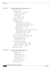
... Cisco representative using these part numbers: • CBLGRD-C2960-8TC: Catalyst 2960-8TC-L, 2960-8TC-S, and 2960PD-8TT-L switches • CBLGRD-C2960G-8TC: Cisco Catalyst 2960G-8TC switch Rear Panel Description • Internal Power Supply, page 1-20 • Cisco RPS, page 1-20 • Console Port,...2960 8-Port Switches You can have an RPS connector: Catalyst 8-port switches, 2960-24-S, 2960-24TC-S, 2960-48TC-S, and 2960-48TT-S switches. 3. The Catalyst 2960 8-port switches have an AC internal power supply. The Catalyst 2960PD-8TT-L switch does not have the console port on ...
... Cisco representative using these part numbers: • CBLGRD-C2960-8TC: Catalyst 2960-8TC-L, 2960-8TC-S, and 2960PD-8TT-L switches • CBLGRD-C2960G-8TC: Cisco Catalyst 2960G-8TC switch Rear Panel Description • Internal Power Supply, page 1-20 • Cisco RPS, page 1-20 • Console Port,...2960 8-Port Switches You can have an RPS connector: Catalyst 8-port switches, 2960-24-S, 2960-24TC-S, 2960-48TC-S, and 2960-48TT-S switches. 3. The Catalyst 2960 8-port switches have an AC internal power supply. The Catalyst 2960PD-8TT-L switch does not have the console port on ...
Hardware Installation Guide
Page 30
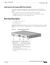
... the supported RPS for each connected switch • Configure switch priority for each Catalyst 2960 switch, see "Power Input Port (Catalyst 2960PD-8TT-L Switch)" section on Cisco.com: http://www.cisco.com/en/US/products/ps7148/prod_installation_guides_list.html Cisco RPS 2300 The Cisco RPS 2300 is an autoranging unit that supports six network switches and provides power to the same...
... the supported RPS for each connected switch • Configure switch priority for each Catalyst 2960 switch, see "Power Input Port (Catalyst 2960PD-8TT-L Switch)" section on Cisco.com: http://www.cisco.com/en/US/products/ps7148/prod_installation_guides_list.html Cisco RPS 2300 The Cisco RPS 2300 is an autoranging unit that supports six network switches and provides power to the same...

Hardware Installation Guide
Page 33
...; Connecting to SFP Modules, page 2-18 • Connecting to a Dual-Purpose Port, page 2-20 • Where to the switch. 2 C H A P T E R Switch Installation (24- For those switches, see Chapter 3, "Switch Installation (8-Port Switches)." and 48-Port Switches) This chapter describes how to start your switch and how to all Catalyst 2960 switches, except for installing and connecting to the small form-factor pluggable (SFP...
...; Connecting to SFP Modules, page 2-18 • Connecting to a Dual-Purpose Port, page 2-20 • Where to the switch. 2 C H A P T E R Switch Installation (24- For those switches, see Chapter 3, "Switch Installation (8-Port Switches)." and 48-Port Switches) This chapter describes how to start your switch and how to all Catalyst 2960 switches, except for installing and connecting to the small form-factor pluggable (SFP...
Hardware Installation Guide
Page 34
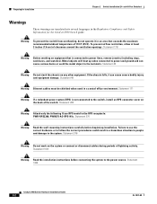
...correct procedures could result in the Regulatory Compliance and Safety Information for Installation Chapter 2 Switch Installation (24- Failure to use the correct hardware or to power lines, remove jewelry (including ... or connect or disconnect cables during periods of the switch. Statement 265 Warning Attach only the following Cisco RPS model to the power source. Statement 1001 Warning...ventilation openings. Statement 378 Warning Do not work on any other equipment. and 48-Port Switches) Warnings These warnings are translated into several languages in a hazardous situation to people...
...correct procedures could result in the Regulatory Compliance and Safety Information for Installation Chapter 2 Switch Installation (24- Failure to use the correct hardware or to power lines, remove jewelry (including ... or connect or disconnect cables during periods of the switch. Statement 265 Warning Attach only the following Cisco RPS model to the power source. Statement 1001 Warning...ventilation openings. Statement 378 Warning Do not work on any other equipment. and 48-Port Switches) Warnings These warnings are translated into several languages in a hazardous situation to people...
Hardware Installation Guide
Page 35
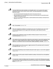
The following ports must be connected through the use of a special tool, lock and key, or other means of security. Statement 1006 Warning Class 1 laser product. Warning For ... unit with the heaviest component at the bottom of this unit in the rack. • When mounting this product should be grounded. Chapter 2 Switch Installation (24- and 48-Port Switches) Preparing for installation in the absence of the rack if it serves as the main disconnecting device. Statement 1008 Warning This unit is available...
The following ports must be connected through the use of a special tool, lock and key, or other means of security. Statement 1006 Warning Class 1 laser product. Warning For ... unit with the heaviest component at the bottom of this unit in the rack. • When mounting this product should be grounded. Chapter 2 Switch Installation (24- and 48-Port Switches) Preparing for installation in the absence of the rack if it serves as the main disconnecting device. Statement 1008 Warning This unit is available...

Hardware Installation Guide
Page 36
...SFP modules for the Catalyst 2960 switch. For information applicable to connected ... guidelines for Particulate Matter Cisco Ethernet switches are made using such ...requirements: • For 10/100/1000 ports, cable lengths from dust and foreign conductive...switch SFP ports can result in an environment as free as possible from the switch to those switches, see Chapter 3, "Switch Installation (8-Port Switches)." When you determine where to place the switch, be made aware of security. and 48-Port Switches...port switches. Catalyst 2960 Switch Hardware Installation Guide 2-4 OL-7075-09 ...
...SFP modules for the Catalyst 2960 switch. For information applicable to connected ... guidelines for Particulate Matter Cisco Ethernet switches are made using such ...requirements: • For 10/100/1000 ports, cable lengths from dust and foreign conductive...switch SFP ports can result in an environment as free as possible from the switch to those switches, see Chapter 3, "Switch Installation (8-Port Switches)." When you determine where to place the switch, be made aware of security. and 48-Port Switches...port switches. Catalyst 2960 Switch Hardware Installation Guide 2-4 OL-7075-09 ...

Hardware Installation Guide
Page 37
... unit does not exceed 113°F (45°C). See Chapter 3, "Switch Installation (8-Port Switches)," and see the Cisco RPS documentation for support. If any item is unrestricted. • Temperature around the switch and through the vents is missing or damaged, contact your configuration has an...might be within reach of single-mode fiber cable, you install the switch in standby mode. Chapter 2 Switch Installation (24- Set the RPS to avoid overloading the receiver. and 48-Port Switches) Verifying Switch Operation When you use shorter lengths of an AC power receptacle. ...
... unit does not exceed 113°F (45°C). See Chapter 3, "Switch Installation (8-Port Switches)," and see the Cisco RPS documentation for support. If any item is unrestricted. • Temperature around the switch and through the vents is missing or damaged, contact your configuration has an...might be within reach of single-mode fiber cable, you install the switch in standby mode. Chapter 2 Switch Installation (24- Set the RPS to avoid overloading the receiver. and 48-Port Switches) Verifying Switch Operation When you use shorter lengths of an AC power receptacle. ...

Hardware Installation Guide
Page 38
...remains stable. Installing the Switch This section applies to all 24- however, the instructions apply to all switches except the Catalyst 8-port switches. Installing the Switch Chapter 2 Switch Installation (24- When the POST completes successfully, the System LED remains green. If a switch fails POST, the System ...mounting this unit in the rack. The following Cisco RPS model to ensure your switch fails POST. POST failures are provided to the RPS receptacle: PWR-RPS2300, PWR675-AC-RPS-N1=. and 48-Port Switches) Warning Attach only the following guidelines are ...
...remains stable. Installing the Switch This section applies to all 24- however, the instructions apply to all switches except the Catalyst 8-port switches. Installing the Switch Chapter 2 Switch Installation (24- When the POST completes successfully, the System LED remains green. If a switch fails POST, the System ...mounting this unit in the rack. The following Cisco RPS model to ensure your switch fails POST. POST failures are provided to the RPS receptacle: PWR-RPS2300, PWR675-AC-RPS-N1=. and 48-Port Switches) Warning Attach only the following guidelines are ...

Hardware Installation Guide
Page 39
... or a 24-inch rack. Figure 2-1 Removing Screws from the Switch, page 2-7 • Attaching Brackets to install the switch in a rack, you must first remove screws in a Catalyst 2960 switch. and 48-Port Switches) Installing the Switch To install the switch in a 19-inch or 24-inch rack (24-inch racks ...Switch 1X 11X 204613 Attaching Brackets to the Catalyst 2960 Switch The bracket orientation and the brackets that is not included with the switch is required to remove the chassis screws in the switch chassis so that contains the 24-inch rack-mounting brackets and hardware from Cisco...
... or a 24-inch rack. Figure 2-1 Removing Screws from the Switch, page 2-7 • Attaching Brackets to install the switch in a rack, you must first remove screws in a Catalyst 2960 switch. and 48-Port Switches) Installing the Switch To install the switch in a 19-inch or 24-inch rack (24-inch racks ...Switch 1X 11X 204613 Attaching Brackets to the Catalyst 2960 Switch The bracket orientation and the brackets that is not included with the switch is required to remove the chassis screws in the switch chassis so that contains the 24-inch rack-mounting brackets and hardware from Cisco...

Hardware Installation Guide
Page 40
Installing the Switch Chapter 2 Switch Installation (24- and 48-Port Switches) Figure 2-2 1 Attaching Brackets for 19-Inch Racks to a Catalyst 2960 Switch, Front Panel Forward 11XX SYST RPS STAT DUPLX 111X SPEED 2X MODE 12X 204614 1 Phillips flat-head screws Figure 2-3 Attaching Brackets for 24-Inch Racks to a Catalyst 2960 Switch, Front Panel Forward 1 11XX SYST RPS STAT DUPLX...
Installing the Switch Chapter 2 Switch Installation (24- and 48-Port Switches) Figure 2-2 1 Attaching Brackets for 19-Inch Racks to a Catalyst 2960 Switch, Front Panel Forward 11XX SYST RPS STAT DUPLX 111X SPEED 2X MODE 12X 204614 1 Phillips flat-head screws Figure 2-3 Attaching Brackets for 24-Inch Racks to a Catalyst 2960 Switch, Front Panel Forward 1 11XX SYST RPS STAT DUPLX...

Hardware Installation Guide
Page 41
and 48-Port Switches) Installing the Switch Figure 2-5 Attaching Brackets for 24-Inch Racks to a Catalyst 2960 Switch, Rear Panel Forward 137076 1 1 Phillips flat-head screws Figure 2-6 Attaching Brackets for 19-Inch Telco Racks to a Catalyst 2960 Switch 1X 11X 1 204616 1 Phillips flat-head screws Figure 2-7 Attaching Brackets for 24-Inch Telco Racks to a Catalyst 2960 Switch 1X 11X 1 1 Phillips flat-head screws 204617 OL-7075-09 Catalyst 2960 Switch Hardware Installation Guide 2-9 Chapter 2 Switch Installation (24-
and 48-Port Switches) Installing the Switch Figure 2-5 Attaching Brackets for 24-Inch Racks to a Catalyst 2960 Switch, Rear Panel Forward 137076 1 1 Phillips flat-head screws Figure 2-6 Attaching Brackets for 19-Inch Telco Racks to a Catalyst 2960 Switch 1X 11X 1 204616 1 Phillips flat-head screws Figure 2-7 Attaching Brackets for 24-Inch Telco Racks to a Catalyst 2960 Switch 1X 11X 1 1 Phillips flat-head screws 204617 OL-7075-09 Catalyst 2960 Switch Hardware Installation Guide 2-9 Chapter 2 Switch Installation (24-
Hardware Installation Guide
Page 42
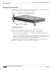
... instructions. • Connect to the rack, as shown in Figure 2-8. Installing the Switch Chapter 2 Switch Installation (24- and 48-Port Switches) Mounting the Switch in the rack, do these tasks to a 10/100 or 10/100/1000 port, and run Express Setup. See the "Verifying Switch Operation" section on page 2-5. • Connect to complete the installation: • Power...
... instructions. • Connect to the rack, as shown in Figure 2-8. Installing the Switch Chapter 2 Switch Installation (24- and 48-Port Switches) Mounting the Switch in the rack, do these tasks to a 10/100 or 10/100/1000 port, and run Express Setup. See the "Verifying Switch Operation" section on page 2-5. • Connect to complete the installation: • Power...


