
Hardware Installation Guide
Page 31
... is 675 W. Figure 1-26 shows the slot on the rear panel. You can order a kit (part number ACS-DSBUASYN=) containing that adapter from Cisco. It automatically senses when the internal power supply of a connected switch fails and provides power to -DB-25 female DTE adapter. The total maximum output... right side panels. Security Slots The Catalyst 2960 8-port switches have security slots on page B-1. Console Port You can connect the switch to a PC by the RPS • Obtain status reports for the RPS power-supply module • Read and monitor backup, failure, and exception history...
... is 675 W. Figure 1-26 shows the slot on the rear panel. You can order a kit (part number ACS-DSBUASYN=) containing that adapter from Cisco. It automatically senses when the internal power supply of a connected switch fails and provides power to -DB-25 female DTE adapter. The total maximum output... right side panels. Security Slots The Catalyst 2960 8-port switches have security slots on page B-1. Console Port You can connect the switch to a PC by the RPS • Obtain status reports for the RPS power-supply module • Read and monitor backup, failure, and exception history...
Hardware Installation Guide
Page 32
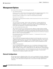
... to configure and manage the switch. Management Options Chapter 1 Product Overview Management Options The Catalyst 2960 switches offer several management options: • Cisco Network Assistant Network Assistant is a PC-based network management GUI with the CLI-Based Setup Program." • CiscoView application The CiscoView device-management application displays the switch image that...
... to configure and manage the switch. Management Options Chapter 1 Product Overview Management Options The Catalyst 2960 switches offer several management options: • Cisco Network Assistant Network Assistant is a PC-based network management GUI with the CLI-Based Setup Program." • CiscoView application The CiscoView device-management application displays the switch image that...

Hardware Installation Guide
Page 90
... the fiber-optic SFP module connections. Each port must match the wave-length specifications on the other end of the switch to a console PC. Copper 1000BASE-T SFP transceivers use standard four twisted-pair, Category 5 or greater cable at lengths up to a terminal. You can order... a kit (part number ACS-DSBUASYN=) containing that adapter from Cisco. The supplied RJ-45-to-DB-9 adapter cable is described in Table B-2 and Table B-3. Cable and Adapter Specifications Appendix B Connector and Cable...
... the fiber-optic SFP module connections. Each port must match the wave-length specifications on the other end of the switch to a console PC. Copper 1000BASE-T SFP transceivers use standard four twisted-pair, Category 5 or greater cable at lengths up to a terminal. You can order... a kit (part number ACS-DSBUASYN=) containing that adapter from Cisco. The supplied RJ-45-to-DB-9 adapter cable is described in Table B-2 and Table B-3. Cable and Adapter Specifications Appendix B Connector and Cable...

Hardware Installation Guide
Page 92
... Cable Specifications Two Twisted-Pair Cable Pinouts Figure B-5 and Figure B-6 show the schematics of two twisted-pair cables for 10/100/1000 Ports Router or PC 1 TP1+ 2 TP13 TPO+ 6 TPO- 4 TP2+ 5 TP27 TP3+ 8 TP3- 4 TP3+ 5 TP37 TP2+ 8 TP2- 65272 Catalyst 2960 Switch Hardware Installation Guide B-6 OL-7075-09 Figure B-5 Switch 3 TD... for connecting to 10BASE-Tand 100BASE-TX-compatible devices. H5578 Figure B-6 Switch 3 TD+ 6 TD- 1 RD+ 2 RD- Two Twisted-Pair Straight-Through Cable Schematic Router or PC 3 RD+ 6 RD- 1 TD+ 2 TD-
... Cable Specifications Two Twisted-Pair Cable Pinouts Figure B-5 and Figure B-6 show the schematics of two twisted-pair cables for 10/100/1000 Ports Router or PC 1 TP1+ 2 TP13 TPO+ 6 TPO- 4 TP2+ 5 TP27 TP3+ 8 TP3- 4 TP3+ 5 TP37 TP2+ 8 TP2- 65272 Catalyst 2960 Switch Hardware Installation Guide B-6 OL-7075-09 Figure B-5 Switch 3 TD... for connecting to 10BASE-Tand 100BASE-TX-compatible devices. H5578 Figure B-6 Switch 3 TD+ 6 TD- 1 RD+ 2 RD- Two Twisted-Pair Straight-Through Cable Schematic Router or PC 3 RD+ 6 RD- 1 TD+ 2 TD-
Hardware Installation Guide
Page 95
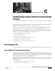
... for mounting your PC or workstation. These steps describe how to the small form-factor pluggable (SFP) modules, see Chapter 1, "Product Overview." Connecting to the switch by using the IP address 10.0.0.1. After the switch is in Chapter 2, "Switch Installation (24- For product overview information, see Chapter 2, "Switch Installation (24- Accessing the CLI...
... for mounting your PC or workstation. These steps describe how to the small form-factor pluggable (SFP) modules, see Chapter 1, "Product Overview." Connecting to the switch by using the IP address 10.0.0.1. After the switch is in Chapter 2, "Switch Installation (24- For product overview information, see Chapter 2, "Switch Installation (24- Accessing the CLI...
Hardware Installation Guide
Page 96
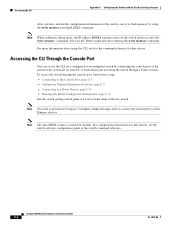
... the switch, save it to flash memory by using the CLI, refer to other Ethernet devices. Accessing the CLI Appendix C Configuring the Switch with your PC or workstation and accessing the switch through a Telnet session. Accessing the CLI Through the Console Port You can access the CLI on a configured or unconfigured...
... the switch, save it to flash memory by using the CLI, refer to other Ethernet devices. Accessing the CLI Appendix C Configuring the Switch with your PC or workstation and accessing the switch through a Telnet session. Accessing the CLI Through the Console Port You can access the CLI on a configured or unconfigured...
Hardware Installation Guide
Page 97
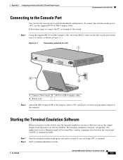
Starting the Terminal Emulation Software Before you power on the switch, start the terminal emulation session so that you are using a PC or terminal. Step 1 Start the terminal-emulation program and open a session if you can use the supplied RJ-45-to the terminal....self-test (POST). OL-7075-09 Catalyst 2960 Switch Hardware Installation Guide C-3 To connect the switch console port to a PC, use the console port to perform the initial configuration. Figure C-1 Connecting a Switch to a PC 1 CONSOLE 137088 3 2 1 Catalyst 2960 switch 3 RJ-45-to-DB-9 adapter cable 2 Power cord Step 2...
Starting the Terminal Emulation Software Before you power on the switch, start the terminal emulation session so that you are using a PC or terminal. Step 1 Start the terminal-emulation program and open a session if you can use the supplied RJ-45-to the terminal....self-test (POST). OL-7075-09 Catalyst 2960 Switch Hardware Installation Guide C-3 To connect the switch console port to a PC, use the console port to perform the initial configuration. Figure C-1 Connecting a Switch to a PC 1 CONSOLE 137088 3 2 1 Catalyst 2960 switch 3 RJ-45-to-DB-9 adapter cable 2 Power cord Step 2...

Hardware Installation Guide
Page 98
... of tests that runs automatically to ensure that shipped with the CLI-Based Setup Program Step 3 Configure the baud rate and character format of the PC or terminal to match these console port default characteristics: • 9600 baud • 8 data bits • 1 stop bit • No ...minute. The System LED blinks green, and the other configuration information necessary for some time and then reflects the switch operating status. Call Cisco technical support representative if your switch fails POST. Note If you plan to use the Network Assistant to configure and manage the switch....
... of tests that runs automatically to ensure that shipped with the CLI-Based Setup Program Step 3 Configure the baud rate and character format of the PC or terminal to match these console port default characteristics: • 9600 baud • 8 data bits • 1 stop bit • No ...minute. The System LED blinks green, and the other configuration information necessary for some time and then reflects the switch operating status. Call Cisco technical support representative if your switch fails POST. Note If you plan to use the Network Assistant to configure and manage the switch....