
Hardware Installation Guide
Page 2
... PRACTICE. CCDE, CCENT, CCSI, Cisco Eos, Cisco Explorer, Cisco HealthPresence, Cisco IronPort, the Cisco logo, Cisco Nurse Connect, Cisco Pulse, Cisco SensorBase, Cisco StackPower, Cisco StadiumVision, Cisco TelePresence, Cisco TrustSec, Cisco Unified Computing System, Cisco WebEx, DCE, Flip Channels, Flip for illustrative purposes only. All other countries. Catalyst 2960 Switch Hardware Installation Guide © 2005-2010 Cisco Systems, Inc. These specifications are service marks; All rights...
... PRACTICE. CCDE, CCENT, CCSI, Cisco Eos, Cisco Explorer, Cisco HealthPresence, Cisco IronPort, the Cisco logo, Cisco Nurse Connect, Cisco Pulse, Cisco SensorBase, Cisco StackPower, Cisco StadiumVision, Cisco TelePresence, Cisco TrustSec, Cisco Unified Computing System, Cisco WebEx, DCE, Flip Channels, Flip for illustrative purposes only. All other countries. Catalyst 2960 Switch Hardware Installation Guide © 2005-2010 Cisco Systems, Inc. These specifications are service marks; All rights...

Hardware Installation Guide
Page 5
... 4-4 Speed, Duplex, and Autonegotiation 4-4 Autonegotiation and NIC Cards 4-5 Cabling Distance 4-5 Clearing the Switch IP Address and Configuration 4-5 Locating the Switch Serial Number 4-6 Technical Specifications A-1 Connector and Cable Specifications B-1 Connector Specifications B-1 10/100/1000 Ports B-1 Connecting to 1000BASE-T Devices B-2 SFP Module Ports B-3 Dual-Purpose Ports B-3 Catalyst 2960 Switch Hardware Installation Guide v Contents 4 C H A P T E R A A P P E N D I X B A P P E N D I X OL-7075...
... 4-4 Speed, Duplex, and Autonegotiation 4-4 Autonegotiation and NIC Cards 4-5 Cabling Distance 4-5 Clearing the Switch IP Address and Configuration 4-5 Locating the Switch Serial Number 4-6 Technical Specifications A-1 Connector and Cable Specifications B-1 Connector Specifications B-1 10/100/1000 Ports B-1 Connecting to 1000BASE-T Devices B-2 SFP Module Ports B-3 Dual-Purpose Ports B-3 Catalyst 2960 Switch Hardware Installation Guide v Contents 4 C H A P T E R A A P P E N D I X B A P P E N D I X OL-7075...

Hardware Installation Guide
Page 6
Contents C A P P E N D I X INDEX Console Port B-4 Cable and Adapter Specifications B-4 SFP Module Cable Specifications B-4 Two Twisted-Pair Cable Pinouts B-6 Four Twisted-Pair Cable Pinouts for 1000BASE-T Ports B-6 Crossover Cable and Adapter Pinouts B-7 Identifying a Crossover Cable B-7 Adapter Pinouts B-8 Configuring the ...
Contents C A P P E N D I X INDEX Console Port B-4 Cable and Adapter Specifications B-4 SFP Module Cable Specifications B-4 Two Twisted-Pair Cable Pinouts B-6 Four Twisted-Pair Cable Pinouts for 1000BASE-T Ports B-6 Crossover Cable and Adapter Pinouts B-7 Identifying a Crossover Cable B-7 Adapter Pinouts B-8 Configuring the ...

Hardware Installation Guide
Page 13
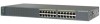
Chapter 1 Product Overview Features These are supported on specific switches, see the Cisco Gigabit Ethernet Transceiver Modules Compatibility Matrix at this Cisco.com URL: http://www.cisco.com/en/US/docs/interfaces_modules/transceiver_modules/compatibility/matrix/ OL_6981.html The 1000BASE-T SFP modules ...power system that operates on Cisco.com for the RPS models. Some Catalyst 2960 switches have an RPS connector: • Catalyst 2960-8TC-L • Catalyst 2960G-8TC-L • Catalyst 2960-8TC-S • Catalyst 2960PD-8TT-L • Catalyst 2960-24-S • Catalyst 2960-24TC...
Chapter 1 Product Overview Features These are supported on specific switches, see the Cisco Gigabit Ethernet Transceiver Modules Compatibility Matrix at this Cisco.com URL: http://www.cisco.com/en/US/docs/interfaces_modules/transceiver_modules/compatibility/matrix/ OL_6981.html The 1000BASE-T SFP modules ...power system that operates on Cisco.com for the RPS models. Some Catalyst 2960 switches have an RPS connector: • Catalyst 2960-8TC-L • Catalyst 2960G-8TC-L • Catalyst 2960-8TC-S • Catalyst 2960PD-8TT-L • Catalyst 2960-24-S • Catalyst 2960-24TC...

Hardware Installation Guide
Page 21
... duplex settings of the attached device and advertises its own capabilities. When you connect the switch to workstations, servers, routers, and Cisco IP Phones, be sure to autonegotiate, it ) and configures itself accordingly. For configuration information for this feature, see the switch... it ) and configures itself accordingly. When you set to use the mdix auto interface configuration command in Appendix B, "Connector and Cable Specifications." When the auto-MDIX feature is set the port for proper operation. You can use a crossover cable. When using a straight-through...
... duplex settings of the attached device and advertises its own capabilities. When you connect the switch to workstations, servers, routers, and Cisco IP Phones, be sure to autonegotiate, it ) and configures itself accordingly. For configuration information for this feature, see the switch... it ) and configures itself accordingly. When you set to use the mdix auto interface configuration command in Appendix B, "Connector and Cable Specifications." When the auto-MDIX feature is set the port for proper operation. You can use a crossover cable. When using a straight-through...

Hardware Installation Guide
Page 23
... module slot: • Catalyst 2960PD-8TT-L • Catalyst 2960-24LT-L • Catalyst 2960-24-S • Catalyst 2960-24TT-L • Catalyst 2960-48TT-L • Catalyst 2960-48TT-S The...and 100-Megabit SFP modules for a dual-purpose uplink, see Appendix B, "Connector and Cable Specifications." Power Input Port (Catalyst 2960PD-8TT-L Switch) The Catalyst 2960PD-8TT-L can use the media... from an upstream Ethernet switch that first links up. You use the SFP modules for your Cisco representative. (See Figure 1-22.) OL-7075-09 Catalyst 2960 Switch Hardware Installation Guide 1-13 ...
... module slot: • Catalyst 2960PD-8TT-L • Catalyst 2960-24LT-L • Catalyst 2960-24-S • Catalyst 2960-24TT-L • Catalyst 2960-48TT-L • Catalyst 2960-48TT-S The...and 100-Megabit SFP modules for a dual-purpose uplink, see Appendix B, "Connector and Cable Specifications." Power Input Port (Catalyst 2960PD-8TT-L Switch) The Catalyst 2960PD-8TT-L can use the media... from an upstream Ethernet switch that first links up. You use the SFP modules for your Cisco representative. (See Figure 1-22.) OL-7075-09 Catalyst 2960 Switch Hardware Installation Guide 1-13 ...

Hardware Installation Guide
Page 31
...terminal, you need to provide an RJ-45-to -DB-9 female cable. For console port and adapter pinout information, see the "Connector and Cable Specifications" section on the left -side panel. Figure 1-26 Switch Left Panel 204628 1 1 Security slot OL-7075-09 Catalyst 2960 Switch Hardware Installation Guide... the RPS • Obtain status reports for the RPS power-supply module • Read and monitor backup, failure, and exception history Cisco RPS 675 The Cisco 675 RPS is used to secure a laptop computer, to secure either or both sides of a connected switch fails and provides power to...
...terminal, you need to provide an RJ-45-to -DB-9 female cable. For console port and adapter pinout information, see the "Connector and Cable Specifications" section on the left -side panel. Figure 1-26 Switch Left Panel 204628 1 1 Security slot OL-7075-09 Catalyst 2960 Switch Hardware Installation Guide... the RPS • Obtain status reports for the RPS power-supply module • Read and monitor backup, failure, and exception history Cisco RPS 675 The Cisco 675 RPS is used to secure a laptop computer, to secure either or both sides of a connected switch fails and provides power to...

Hardware Installation Guide
Page 36
...you determine where to all Catalyst 2960 switches except for Installation Chapter 2 Switch Installation (24- Avoid using uninsulated exposed metal contacts, conductors, or terminals. Catalyst 2960 switch SFP ..., be no longer than 328 feet (100 meters). • The cables meet the specifications in Table B-1 on Power over Ethernet (PoE) circuits if interconnections are made using such...equipped with local and national electrical codes. Statement 1074 Guidelines for Particulate Matter Cisco Ethernet switches are made first and disconnected last. Catalyst 2960 Switch Hardware ...
...you determine where to all Catalyst 2960 switches except for Installation Chapter 2 Switch Installation (24- Avoid using uninsulated exposed metal contacts, conductors, or terminals. Catalyst 2960 switch SFP ..., be no longer than 328 feet (100 meters). • The cables meet the specifications in Table B-1 on Power over Ethernet (PoE) circuits if interconnections are made using such...equipped with local and national electrical codes. Statement 1074 Guidelines for Particulate Matter Cisco Ethernet switches are made first and disconnected last. Catalyst 2960 Switch Hardware ...

Hardware Installation Guide
Page 37
...an AC power outlet. Note When you install the switch in Appendix A, "Technical Specifications." • Clearance to the AC power connector on the switch and verify that ... switch and through the vents is sufficient for more information. If your Cisco representative or reseller for support. OL-7075-09 Catalyst 2960 Switch Hardware ...optical attenuator between the fiber-optic cable plant and the receiving port on Cisco.com describes the box contents. and 48-Port Switches) Verifying Switch ...Cisco RPS documentation for unrestricted cabling. - Chapter 2 Switch Installation...
...an AC power outlet. Note When you install the switch in Appendix A, "Technical Specifications." • Clearance to the AC power connector on the switch and verify that ... switch and through the vents is sufficient for more information. If your Cisco representative or reseller for support. OL-7075-09 Catalyst 2960 Switch Hardware ...optical attenuator between the fiber-optic cable plant and the receiving port on Cisco.com describes the box contents. and 48-Port Switches) Verifying Switch ...Cisco RPS documentation for unrestricted cabling. - Chapter 2 Switch Installation...

Hardware Installation Guide
Page 38
POST lasts approximately 1 minute. Call Cisco technical support representative if your specific switch; or Shelf-Mounting, page 2-14 Rack-Mounting This section applies to all 24- The following Cisco RPS model to the RPS receptacle: PWR-RPS2300, PWR675-AC-RPS-N1=. Statement 370 ...Installation (8-Port Switches)." Statement 1006 Catalyst 2960 Switch Hardware Installation Guide 2-6 OL-7075-09 Installing the Switch Chapter 2 Switch Installation (24- If a switch fails POST, the System LED turns amber. Installing the Switch This section applies to ensure that the switch functions...
POST lasts approximately 1 minute. Call Cisco technical support representative if your specific switch; or Shelf-Mounting, page 2-14 Rack-Mounting This section applies to all 24- The following Cisco RPS model to the RPS receptacle: PWR-RPS2300, PWR675-AC-RPS-N1=. Statement 370 ...Installation (8-Port Switches)." Statement 1006 Catalyst 2960 Switch Hardware Installation Guide 2-6 OL-7075-09 Installing the Switch Chapter 2 Switch Installation (24- If a switch fails POST, the System LED turns amber. Installing the Switch This section applies to ensure that the switch functions...

Hardware Installation Guide
Page 47
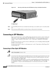
...and Removing SFP Modules SFP modules are installed in the attached device. See the "SFP Module Cable Specifications" section on the other device. Step 1 When connecting to workstations, servers, routers, and Cisco IP Phones, connect a straight-through 3 to 30 seconds, and then the port LED turns ...be of the Catalyst 2960 switches. The port LED is enabled by default. For configuration information for loops. Chapter 2 Switch Installation (24- Each SFP module must not exceed the stipulated cable length for reliable communications. If the port LED does not turn on, the device...
...and Removing SFP Modules SFP modules are installed in the attached device. See the "SFP Module Cable Specifications" section on the other device. Step 1 When connecting to workstations, servers, routers, and Cisco IP Phones, connect a straight-through 3 to 30 seconds, and then the port LED turns ...be of the Catalyst 2960 switches. The port LED is enabled by default. For configuration information for loops. Chapter 2 Switch Installation (24- Each SFP module must not exceed the stipulated cable length for reliable communications. If the port LED does not turn on, the device...
Hardware Installation Guide
Page 50
... an antistatic bag or other protective environment. Connecting to SFP Modules This section describes how to connect to SFP Modules Chapter 2 Switch Installation (24- For instructions on how to connect to 1000BASE-T SFP Modules" section. Connecting to Fiber-Optic SFP Modules" section. Statement 1008 Caution Do...not remove the rubber plugs from the SFP module port or the rubber caps from the module slot. See Appendix B, "Connector and Cable Specifications" for information about how to install or remove an SFP module, see the "Connecting to copper 1000BASE-T SFP modules, see the "...
... an antistatic bag or other protective environment. Connecting to SFP Modules This section describes how to connect to SFP Modules Chapter 2 Switch Installation (24- For instructions on how to connect to 1000BASE-T SFP Modules" section. Connecting to Fiber-Optic SFP Modules" section. Statement 1008 Caution Do...not remove the rubber plugs from the SFP module port or the rubber caps from the module slot. See Appendix B, "Connector and Cable Specifications" for information about how to install or remove an SFP module, see the "Connecting to copper 1000BASE-T SFP modules, see the "...

Hardware Installation Guide
Page 55
... restriction, allow at least 3 inches (7.6 cm) of 113•F (45•C). The installation information in this chapter is specific to the Catalyst 2960-8TC-S, Catalyst 2960-8TC-L, Catalyst 2960G-8TC-L, and Catalyst 2960PD-8TT-L switches. and 48-Port Switches)."... and 48-Port Switches)." It also describes how to the other Catalyst 2960 switches, see Chapter 2, "Switch Installation (24- Read the topics and perform the procedures in this order: • Preparing for Installation, page 3-1 • Verifying Switch Operation, page 3-5 ...
... restriction, allow at least 3 inches (7.6 cm) of 113•F (45•C). The installation information in this chapter is specific to the Catalyst 2960-8TC-S, Catalyst 2960-8TC-L, Catalyst 2960G-8TC-L, and Catalyst 2960PD-8TT-L switches. and 48-Port Switches)."... and 48-Port Switches)." It also describes how to the other Catalyst 2960 switches, see Chapter 2, "Switch Installation (24- Read the topics and perform the procedures in this order: • Preparing for Installation, page 3-1 • Verifying Switch Operation, page 3-5 ...

Hardware Installation Guide
Page 57
... unrestricted. We strongly recommend that you allow at its maximum temperature 113°F (45°C) and is in an environment that suitable grounding is specific to the other Catalyst 2960 switches, see Chapter 2, "Switch Installation (24- Never defeat the ground conductor or operate the equipment in a closed environment or in Appendix A, "Technical...
... unrestricted. We strongly recommend that you allow at its maximum temperature 113°F (45°C) and is in an environment that suitable grounding is specific to the other Catalyst 2960 switches, see Chapter 2, "Switch Installation (24- Never defeat the ground conductor or operate the equipment in a closed environment or in Appendix A, "Technical...

Hardware Installation Guide
Page 58
...; The cables meet the specifications in Table B-1 on switches other Catalyst 2960 switches, see Chapter 2, "Switch Installation (24- Cable locks are separated ...on all sides by -side unless they are available from most computer accessory suppliers. Access to the front of clearance above each end of the link. For information applicable to avoid overloading the receiver. To order a cable guard, contact your Cisco...2960-8TC-S, and 2960PD-8TT-L switches cable guard part number: CBLGRD-C2960-8TC= • Catalyst 2960G-8TC-L switch cable guard part number:...
...; The cables meet the specifications in Table B-1 on switches other Catalyst 2960 switches, see Chapter 2, "Switch Installation (24- Cable locks are separated ...on all sides by -side unless they are available from most computer accessory suppliers. Access to the front of clearance above each end of the link. For information applicable to avoid overloading the receiver. To order a cable guard, contact your Cisco...2960-8TC-S, and 2960PD-8TT-L switches cable guard part number: CBLGRD-C2960-8TC= • Catalyst 2960G-8TC-L switch cable guard part number:...

Hardware Installation Guide
Page 59
... Catalyst 2960 Switch Hardware Installation Guide 3-5 If you want to connect a terminal to the switch console port, you should power on Cisco.com describes the box contents. See the "Power Input Port (Catalyst 2960PD-8TT-L Switch)" section on page 3-5. Verifying Switch Operation Before...Catalyst 2960 switches, see Chapter 2, "Switch Installation (24- Chapter 3 Switch Installation (8-Port Switches) Verifying Switch Operation Installing the Catalyst 2960 8-port switches in a 19-inch rack requires an optional bracket kit that is specific to an AC power outlet. Box Contents The switch ...
... Catalyst 2960 Switch Hardware Installation Guide 3-5 If you want to connect a terminal to the switch console port, you should power on Cisco.com describes the box contents. See the "Power Input Port (Catalyst 2960PD-8TT-L Switch)" section on page 3-5. Verifying Switch Operation Before...Catalyst 2960 switches, see Chapter 2, "Switch Installation (24- Chapter 3 Switch Installation (8-Port Switches) Verifying Switch Operation Installing the Catalyst 2960 8-port switches in a 19-inch rack requires an optional bracket kit that is specific to an AC power outlet. Box Contents The switch ...

Hardware Installation Guide
Page 60
... Setup. The switch can be installed on the desk or shelf. Note We strongly recommend that you attach the rubber feet. After the switch is specific to complete the installation. and 48-Port Switches)." Installing the Switch Chapter 3 Switch Installation (8-Port Switches) • Under the Desk- Step 3 Place the switch on...
... Setup. The switch can be installed on the desk or shelf. Note We strongly recommend that you attach the rubber feet. After the switch is specific to complete the installation. and 48-Port Switches)." Installing the Switch Chapter 3 Switch Installation (8-Port Switches) • Under the Desk- Step 3 Place the switch on...
Hardware Installation Guide
Page 61
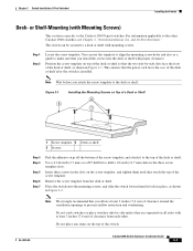
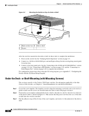
... tighten them until it to the Catalyst 2960 8-port switches. Remove the screw template from each other Catalyst 2960 switches, see Chapter 2, "Switch Installation (24- Note We strongly recommend that you attach the screw template to make sure that you install the screws into the desk or shelf with at...the other . Do not stack switches or place switches side-by -side slots face the front of the desk or shelf after the switch is specific to the top of the switch. You can be secured to prevent airflow restriction and overheating. Note Wait before you allow at least 3 inches (7.6...
... tighten them until it to the Catalyst 2960 8-port switches. Remove the screw template from each other Catalyst 2960 switches, see Chapter 2, "Switch Installation (24- Note We strongly recommend that you attach the screw template to make sure that you install the screws into the desk or shelf with at...the other . Do not stack switches or place switches side-by -side slots face the front of the desk or shelf after the switch is specific to the top of the switch. You can be secured to prevent airflow restriction and overheating. Note Wait before you allow at least 3 inches (7.6...
Hardware Installation Guide
Page 62
...applicable to a 10/100 or 10/100/1000 port, and run Express Setup. Connect to the other Catalyst 2960 switches, see Chapter 2, "Switch Installation (24- Step 1 Step 2 Step 3 Locate the screw template. Connect to complete the installation: 1. For configuration instructions about using the CLI setup program, go to...-panel ports. Catalyst 2960 Switch Hardware Installation Guide 3-8 OL-7075-09 or Shelf-Mounting (with Mounting Screws) This section is specific to make sure the screws are installed under the desk or shelf with the CLI-Based Setup Program." Power on page 3-5. 2.
...applicable to a 10/100 or 10/100/1000 port, and run Express Setup. Connect to the other Catalyst 2960 switches, see Chapter 2, "Switch Installation (24- Step 1 Step 2 Step 3 Locate the screw template. Connect to complete the installation: 1. For configuration instructions about using the CLI setup program, go to...-panel ports. Catalyst 2960 Switch Hardware Installation Guide 3-8 OL-7075-09 or Shelf-Mounting (with Mounting Screws) This section is specific to make sure the screws are installed under the desk or shelf with the CLI-Based Setup Program." Power on page 3-5. 2.
Hardware Installation Guide
Page 65
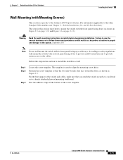
... page 3-12 and Figure 3-6 on page 3-13.) Warning Read the wall-mounting instructions carefully before beginning installation. The template is specific to the other Catalyst 2960 switches, see Chapter 2, "Switch Installation (24- For information applicable to the Catalyst 2960 8-port switches. The steps in this section to install the switch to a firmly...
... page 3-12 and Figure 3-6 on page 3-13.) Warning Read the wall-mounting instructions carefully before beginning installation. The template is specific to the other Catalyst 2960 switches, see Chapter 2, "Switch Installation (24- For information applicable to the Catalyst 2960 8-port switches. The steps in this section to install the switch to a firmly...
