
Hardware Installation Guide
Page 31
...or both sides of the switch. Figure 1-26 Switch Left Panel 204628 1 1 Security slot OL-7075-09 Catalyst 2960 Switch Hardware Installation Guide 1-21 The Cisco RPS 675 has two output levels: -48 V and 12 V. Security Slots The Catalyst 2960 8-port switches have security slots on the left -side panel..., see the "Connector and Cable Specifications" section on the Catalyst 2960 8-port switches is 675 W. Console Port You can connect the switch to a PC by the RPS • Obtain status reports for the RPS power-supply module • Read and monitor backup, failure, and exception history...
...or both sides of the switch. Figure 1-26 Switch Left Panel 204628 1 1 Security slot OL-7075-09 Catalyst 2960 Switch Hardware Installation Guide 1-21 The Cisco RPS 675 has two output levels: -48 V and 12 V. Security Slots The Catalyst 2960 8-port switches have security slots on the left -side panel..., see the "Connector and Cable Specifications" section on the Catalyst 2960 8-port switches is 675 W. Console Port You can connect the switch to a PC by the RPS • Obtain status reports for the RPS power-supply module • Read and monitor backup, failure, and exception history...
Hardware Installation Guide
Page 32
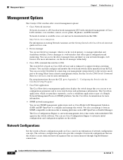
... firewalls. Management Options Chapter 1 Product Overview Management Options The Catalyst 2960 switches offer several management options: • Cisco Network Assistant Network Assistant is a web interface that offers quick configuration and monitoring. Device manager is a PC-based network management GUI with embedded CNS agents in your management station directly to view switch status...
... firewalls. Management Options Chapter 1 Product Overview Management Options The Catalyst 2960 switches offer several management options: • Cisco Network Assistant Network Assistant is a web interface that offers quick configuration and monitoring. Device manager is a PC-based network management GUI with embedded CNS agents in your management station directly to view switch status...

Hardware Installation Guide
Page 90
You can order a kit (part number ACS-DSBUASYN=) containing that adapter from Cisco. Cable and Adapter Specifications These sections describe the cables and adapters used to connect the console port of the cable, and for the fiber-optic ... Table B-1 lists the cable specifications for reliable communications, the cable must match the wave-length specifications on the other end of the switch to a console PC. Copper 1000BASE-T SFP transceivers use standard four twisted-pair, Category 5 or greater cable at lengths up to a terminal.
You can order a kit (part number ACS-DSBUASYN=) containing that adapter from Cisco. Cable and Adapter Specifications These sections describe the cables and adapters used to connect the console port of the cable, and for the fiber-optic ... Table B-1 lists the cable specifications for reliable communications, the cable must match the wave-length specifications on the other end of the switch to a console PC. Copper 1000BASE-T SFP transceivers use standard four twisted-pair, Category 5 or greater cable at lengths up to a terminal.

Hardware Installation Guide
Page 92
... Twisted-Pair Cable Pinouts for 1000BASE-T Ports Figure B-7 and Figure B-8 show the schematics of four twisted-pair cables for 10/100/1000 Ports Router or PC 1 TP1+ 2 TP13 TPO+ 6 TPO- 4 TP2+ 5 TP27 TP3+ 8 TP3- 4 TP3+ 5 TP37 TP2+ 8 TP2- 65272 Catalyst 2960 Switch Hardware Installation Guide B-6 OL-7075-09 Figure B-7 Switch 1 TPO...
... Twisted-Pair Cable Pinouts for 1000BASE-T Ports Figure B-7 and Figure B-8 show the schematics of four twisted-pair cables for 10/100/1000 Ports Router or PC 1 TP1+ 2 TP13 TPO+ 6 TPO- 4 TP2+ 5 TP27 TP3+ 8 TP3- 4 TP3+ 5 TP37 TP2+ 8 TP2- 65272 Catalyst 2960 Switch Hardware Installation Guide B-6 OL-7075-09 Figure B-7 Switch 1 TPO...
Hardware Installation Guide
Page 95
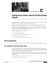
... user EXEC command. For installation procedures for a standalone switch. After the switch is in Chapter 2, "Switch Installation (24- Connecting to the switch by placing the switch in this chapter to the Console Port, page C-3 3. These steps describe...safety warnings in Express Setup mode, open a Telnet session to a Power Source, page C-4 5. For product overview information, see Chapter 2, "Switch Installation (24- Entering the Initial Configuration Information, page C-4 Accessing the CLI For an unconfigured switch, you connect the switch to do an installation: 1. C A P...
... user EXEC command. For installation procedures for a standalone switch. After the switch is in Chapter 2, "Switch Installation (24- Connecting to the switch by placing the switch in this chapter to the Console Port, page C-3 3. These steps describe...safety warnings in Express Setup mode, open a Telnet session to a Power Source, page C-4 5. For product overview information, see Chapter 2, "Switch Installation (24- Entering the Initial Configuration Information, page C-4 Accessing the CLI For an unconfigured switch, you connect the switch to do an installation: 1. C A P...
Hardware Installation Guide
Page 96
... configuration information for this feature, see the switch software configuration guide or the switch command reference. Accessing the CLI Appendix C Configuring the Switch with your PC or workstation and accessing the switch through a Telnet session. You lose the Telnet connection after entering the write memory command. For more information about using...
... configuration information for this feature, see the switch software configuration guide or the switch command reference. Accessing the CLI Appendix C Configuring the Switch with your PC or workstation and accessing the switch through a Telnet session. You lose the Telnet connection after entering the write memory command. For more information about using...
Hardware Installation Guide
Page 97
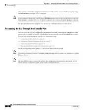
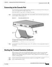
... Step 2 Attach the DB-9 female DTE of a switch, as Hyperterminal or Procomm Plus-makes communication between the switch and your PC or terminal possible. Starting the Terminal Emulation Software Before you power on the switch, start the terminal emulation session so that you are using... a PC or terminal. Step 2 Start a terminal-emulation session. OL-7075-09 Catalyst 2960 Switch Hardware Installation Guide C-3 Step 1 Start the terminal-...
... Step 2 Attach the DB-9 female DTE of a switch, as Hyperterminal or Procomm Plus-makes communication between the switch and your PC or terminal possible. Starting the Terminal Emulation Software Before you power on the switch, start the terminal emulation session so that you are using... a PC or terminal. Step 2 Start a terminal-emulation session. OL-7075-09 Catalyst 2960 Switch Hardware Installation Guide C-3 Step 1 Start the terminal-...

Hardware Installation Guide
Page 98
... it begins the power-on a switch rear panel. POST failures are connecting the switch to a Cisco redundant power system (RPS), refer to complete the setup program, which runs automatically after the switch ...C Configuring the Switch with the CLI-Based Setup Program Step 3 Configure the baud rate and character format of the PC or terminal to match these console port default characteristics: • 9600 baud • 8 data bits • ... ensure that shipped with your RPS. Call Cisco technical support representative if your switch, the PC or terminal displays the bootloader sequence.
... it begins the power-on a switch rear panel. POST failures are connecting the switch to a Cisco redundant power system (RPS), refer to complete the setup program, which runs automatically after the switch ...C Configuring the Switch with the CLI-Based Setup Program Step 3 Configure the baud rate and character format of the PC or terminal to match these console port default characteristics: • 9600 baud • 8 data bits • ... ensure that shipped with your RPS. Call Cisco technical support representative if your switch, the PC or terminal displays the bootloader sequence.