
Administration Guide
Page 2
... Viewing On-line Help 11 5 Using the Console 12 Connecting to Your Switch with HyperTerminal 12 Connecting to the Switch with Telnet 15 Logging On to the Console 15 Selecting Menu Options and Actions 15 Using the Switch Main Menu 16 System Configuration 16 System Information 17 Management Settings 19 Username & Password Settings 24 Security Settings 25 VLAN Management 28 IP Configuration 29 File Management 43 Restore System Default Settings 46 Reset to Factory Settings 46 Reboot System 46 Stack Configuration 47 Port Status 47 Port Status 48 PoE Status...
... Viewing On-line Help 11 5 Using the Console 12 Connecting to Your Switch with HyperTerminal 12 Connecting to the Switch with Telnet 15 Logging On to the Console 15 Selecting Menu Options and Actions 15 Using the Switch Main Menu 16 System Configuration 16 System Information 17 Management Settings 19 Username & Password Settings 24 Security Settings 25 VLAN Management 28 IP Configuration 29 File Management 43 Restore System Default Settings 46 Reset to Factory Settings 46 Reboot System 46 Stack Configuration 47 Port Status 47 Port Status 48 PoE Status...

Administration Guide
Page 4
... 5, "Using the Console" This chapter describes the use the console interface to bridge your different networks. This user guide covers the steps for setting up , and configure it to configure the Switch. The Switch features monitoring and configuration via your web browser, making it up and using the Switch. • Chapter 2, "Getting to Know the SFE2010/SFE2010P" This chapter describes the ports, LEDs, and other Linksys switches or devices. What's in this User Guide? These instructions should...
... 5, "Using the Console" This chapter describes the use the console interface to bridge your different networks. This user guide covers the steps for setting up , and configure it to configure the Switch. The Switch features monitoring and configuration via your web browser, making it up and using the Switch. • Chapter 2, "Getting to Know the SFE2010/SFE2010P" This chapter describes the ports, LEDs, and other Linksys switches or devices. What's in this User Guide? These instructions should...
Administration Guide
Page 5
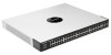
... a pin or paper clip into the RESET opening. All customized user settings will reset to indicate that affordably expand the capability of the Linksys system. A green FAN LED lights up to indicate a functional network link through the corresponding port with an attached device. These two versions are functionally identical except the SFE2010P model offers Power-over Ethernet cable. These functions are 48-port, layer-2 Ethernet switches that the Switch is operating properly. A blinking red FAN LED indicates...
... a pin or paper clip into the RESET opening. All customized user settings will reset to indicate that affordably expand the capability of the Linksys system. A green FAN LED lights up to indicate a functional network link through the corresponding port with an attached device. These two versions are functionally identical except the SFE2010P model offers Power-over Ethernet cable. These functions are 48-port, layer-2 Ethernet switches that the Switch is operating properly. A blinking red FAN LED indicates...

Administration Guide
Page 6
... enables each port to automatically detect the speed of up to 1000Mbps. The mini-GBIC (gigabit interface converter) port is a connection point for use RJ-45 connectors. Ports G1-G2 are reserved for a mini-GBIC expansion module, so the Switch can be uplinked via fiber to another switch. In stacking mode, ports G1 and G2 are Ethernet (802.3ab) uplink ports which use as stacking ports. Each mini-GBIC port provides a link...
... enables each port to automatically detect the speed of up to 1000Mbps. The mini-GBIC (gigabit interface converter) port is a connection point for use RJ-45 connectors. Ports G1-G2 are reserved for a mini-GBIC expansion module, so the Switch can be uplinked via fiber to another switch. In stacking mode, ports G1 and G2 are Ethernet (802.3ab) uplink ports which use as stacking ports. Each mini-GBIC port provides a link...

Administration Guide
Page 7
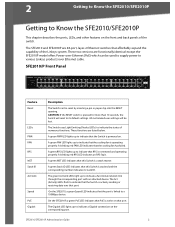
Refer to Chapter 4: Using the Console Interface for Configuration for configuration using your PC's HyperTerminal program. The Console port is where you can connect a serial cable to Know the SFE2010/SFE2010P SFE2010/P Back Panel Feature Power Console RPS Description The Power port is where you will connect the power cord. Redundant Power Supply (Linksys RPS1000) SFE2010/SFE2010P Administration Guide 4 Getting to a PC's serial port for more information.
Refer to Chapter 4: Using the Console Interface for Configuration for configuration using your PC's HyperTerminal program. The Console port is where you can connect a serial cable to Know the SFE2010/SFE2010P SFE2010/P Back Panel Feature Power Console RPS Description The Power port is where you will connect the power cord. Redundant Power Supply (Linksys RPS1000) SFE2010/SFE2010P Administration Guide 4 Getting to a PC's serial port for more information.

Administration Guide
Page 9
... near an AC power source. Desktop Placement 1. SFE2010/SFE2010P Administration Guide 6 Either set the Ethernet switch on its four rubber feet for desktop placement, mount it on a wall with the switch. Before You Install the Switch... NOTE: The four supplied mounting brackets can be easily connected. • Keep cabling away from sources of electrical noise, power lines, and fluorescent lighting fixtures. • Position the switch away from water...
... near an AC power source. Desktop Placement 1. SFE2010/SFE2010P Administration Guide 6 Either set the Ethernet switch on its four rubber feet for desktop placement, mount it on a wall with the switch. Before You Install the Switch... NOTE: The four supplied mounting brackets can be easily connected. • Keep cabling away from sources of electrical noise, power lines, and fluorescent lighting fixtures. • Position the switch away from water...

Administration Guide
Page 11
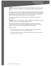
... Ethernet switch. 4. Repeat steps 1 through 3 for re-installation. NOTE: If connecting an Ethernet switch to an SVR3000 router, connect it to the documentation supplied with appropriate screws (not supplied). Place a rack mount bracket next to a wall, the ports can be oriented in step 1). Connecting Devices Connecting the Cables Wall-Mount Placement 1. The wall mount brackets should point towards the bottom of the Ethernet switch. 5. Retain the screws for the other network device. 3. When the switch is mounted...
... Ethernet switch. 4. Repeat steps 1 through 3 for re-installation. NOTE: If connecting an Ethernet switch to an SVR3000 router, connect it to the documentation supplied with appropriate screws (not supplied). Place a rack mount bracket next to a wall, the ports can be oriented in step 1). Connecting Devices Connecting the Cables Wall-Mount Placement 1. The wall mount brackets should point towards the bottom of the Ethernet switch. 5. Retain the screws for the other network device. 3. When the switch is mounted...
Administration Guide
Page 12
...use the console interface to configure the Ethernet switch, then connect the supplied serial cable to the console port (located on the Ethernet switch. Connect the supplied power cord to the Ethernet switch. Each active port's corresponding Act/Link LED will light up . 8. Proceed as HyperTerminal.) 6. SFE2010/SFE2010P Administration Guide 9 If a port has an active Gigabit connection, then its corresponding Gigabit LED will use the console interface to configure the Ethernet switch, proceed to "Console Configuration" section on page 33 for directions. • If you use the Web...
...use the console interface to configure the Ethernet switch, then connect the supplied serial cable to the console port (located on the Ethernet switch. Connect the supplied power cord to the Ethernet switch. Each active port's corresponding Act/Link LED will light up . 8. Proceed as HyperTerminal.) 6. SFE2010/SFE2010P Administration Guide 9 If a port has an active Gigabit connection, then its corresponding Gigabit LED will use the console interface to configure the Ethernet switch, proceed to "Console Configuration" section on page 33 for directions. • If you use the Web...

Administration Guide
Page 13
The default IP address is connected to the same network as the switch. Using Menus in the Web-Based Utility Use the left navigation panel to configure the switch. This utility is accessed through your web browser. SFE2010/SFE2010P Administration Guide 10 4 Web Utility Configuration Connecting to the Switch with the Web-Based Utility You can connect to the switch using a standard web browser on page 11 Connecting to the Switch with the Web-Based Utility Web Utility Configuration This...
The default IP address is connected to the same network as the switch. Using Menus in the Web-Based Utility Use the left navigation panel to configure the switch. This utility is accessed through your web browser. SFE2010/SFE2010P Administration Guide 10 4 Web Utility Configuration Connecting to the Switch with the Web-Based Utility You can connect to the switch using a standard web browser on page 11 Connecting to the Switch with the Web-Based Utility Web Utility Configuration This...

Administration Guide
Page 15
... Enter key. SFE2010/SFE2010P Administration Guide 12 NOTE: The switch also can save the settings to use each time you connect to your switch. Before you use HyperTerminal to connect to your switch for basic configuration of the switch and management of your PC. Telnet to your switch. You can be performed through a telnet connection. 5 Using the Console Connecting to Your Switch with HyperTerminal Using the Console This chapter describes the use of the switch console, which is admin...
... Enter key. SFE2010/SFE2010P Administration Guide 12 NOTE: The switch also can save the settings to use each time you connect to your switch. Before you use HyperTerminal to connect to your switch for basic configuration of the switch and management of your PC. Telnet to your switch. You can be performed through a telnet connection. 5 Using the Console Connecting to Your Switch with HyperTerminal Using the Console This chapter describes the use of the switch console, which is admin...
Administration Guide
Page 18
Open a command line editor and enter telnet . Select Enter to login, enter the default login and password: admin The Switch Main Menu appears. When prompted to enter the CLI interface. Press the menu number and then press Enter key to the Console 1. When the Login screen appears, select Edit and enter admin in numeric order. Start HyperTerminal and open the connection that is highlighted by the cursor. When the blinking cursor appears...
Open a command line editor and enter telnet . Select Enter to login, enter the default login and password: admin The Switch Main Menu appears. When prompted to enter the CLI interface. Press the menu number and then press Enter key to the Console 1. When the Login screen appears, select Edit and enter admin in numeric order. Start HyperTerminal and open the connection that is highlighted by the cursor. When the blinking cursor appears...

Administration Guide
Page 19
... (see page 53) System Configuration The System Configuration Menu provides access to screens where you can manage system information, view or modify management settings, set up user accounts, and manage security settings. Using the Console Using the Switch Main Menu Using the Switch Main Menu The Switch Main Menu provides access to screens that you need to restore default settings, reset the switch to the factory default configuration, or reboot the system. 1. System Configuration (see page 47) 3. Port Status (see page 16) 2.
... (see page 53) System Configuration The System Configuration Menu provides access to screens where you can manage system information, view or modify management settings, set up user accounts, and manage security settings. Using the Console Using the Switch Main Menu Using the Switch Main Menu The Switch Main Menu provides access to screens that you need to restore default settings, reset the switch to the factory default configuration, or reboot the system. 1. System Configuration (see page 47) 3. Port Status (see page 16) 2.

Administration Guide
Page 20
Username & Password Settings (see page 28) 6. VLAN Management (see page 24) 4. Restore System Default Settings (see page 46) 11. System Configuration. 2. System Information. 3. When you can view firmware version information and general system information. 1. Reboot System (see page 46) 9. General Information (see page 46) 10. SFE2010/SFE2010P Administration Guide 17 File Management (see page 18) 2. System Information The System Information menu provides access to the previous menu.) To open this...
Username & Password Settings (see page 28) 6. VLAN Management (see page 24) 4. Restore System Default Settings (see page 46) 11. System Configuration. 2. System Information. 3. When you can view firmware version information and general system information. 1. Reboot System (see page 46) 9. General Information (see page 46) 10. SFE2010/SFE2010P Administration Guide 17 File Management (see page 18) 2. System Information The System Information menu provides access to the previous menu.) To open this...
Administration Guide
Page 23
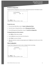
... the cursor to the Action list. 3. From the Switch Main Menu, select 1. Select Save to the Action list. Telnet Configuration Use the Telnet Configuration screen to view or change the baud rate of the Ethernet switch. To change the time-out settings. Using the Console System Configuration Serial Port Configuration Use the Serial Port Configuration screen to view or change the baud rate of the serial port: 1. To open this screen: 1. Management Settings. 3. From the Management Settings Menu, choose 1. Press the Esc key to move the cursor...
... the cursor to the Action list. 3. From the Switch Main Menu, select 1. Select Save to the Action list. Telnet Configuration Use the Telnet Configuration screen to view or change the baud rate of the Ethernet switch. To change the time-out settings. Using the Console System Configuration Serial Port Configuration Use the Serial Port Configuration screen to view or change the baud rate of the serial port: 1. To open this screen: 1. Management Settings. 3. From the Management Settings Menu, choose 1. Press the Esc key to move the cursor...

Administration Guide
Page 28
... Edit, and then make your changes. 4. You must enter the same password in length. Show Certificate (see page 26) 2. Disable Active Management Access Profile (see page 27) 0.Back (Select to return to the Action list. 3. SFE2010/SFE2010P Administration Guide 25 From the System Configuration Menu, select 3. Using the Console System Configuration NOTE: The default user is "admin" with no password. Username & Password Settings. You also can be 20 characters...
... Edit, and then make your changes. 4. You must enter the same password in length. Show Certificate (see page 26) 2. Disable Active Management Access Profile (see page 27) 0.Back (Select to return to the Action list. 3. SFE2010/SFE2010P Administration Guide 25 From the System Configuration Menu, select 3. Using the Console System Configuration NOTE: The default user is "admin" with no password. Username & Password Settings. You also can be 20 characters...
Administration Guide
Page 49
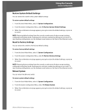
...stacking configuration, use the hardware reset button on the front of the Ethernet switch. To restore factory default settings 1. System Configuration. 2. From the Switch Main Menu, select 1. To restore system default settings 1. From the Switch Main Menu, select 1. System Configuration. 2. NOTE: Restoring default settings from the console or web resets all values except stacking configuration (stacking mode, stacking ports, and auto-numbering settings are not reset). Restore Factory Settings. 3. NOTE: Restoring factory settings from the console or web resets all...
...stacking configuration, use the hardware reset button on the front of the Ethernet switch. To restore factory default settings 1. System Configuration. 2. From the Switch Main Menu, select 1. To restore system default settings 1. From the Switch Main Menu, select 1. System Configuration. 2. NOTE: Restoring default settings from the console or web resets all values except stacking configuration (stacking mode, stacking ports, and auto-numbering settings are not reset). Restore Factory Settings. 3. NOTE: Restoring factory settings from the console or web resets all...

Administration Guide
Page 52
... can use the up or down arrow keys to scroll through all the ports on the Ethernet switch. PoE Settings (see page 49) 2. From the Switch Main Menu, press 3. Port Configuration. 2. Poe Status. Port Configuration. You can use the Port Settings screen to the previous screen.) From the Switch Main Menu, press 3. Port Settings (see page 50) 0.Back (Select to return to specify the auto negotiation status, port speed, duplex mode, and flow control settings. SFE2010/SFE2010P Administration Guide...
... can use the up or down arrow keys to scroll through all the ports on the Ethernet switch. PoE Settings (see page 49) 2. From the Switch Main Menu, press 3. Port Configuration. 2. Poe Status. Port Configuration. You can use the Port Settings screen to the previous screen.) From the Switch Main Menu, press 3. Port Settings (see page 50) 0.Back (Select to return to specify the auto negotiation status, port speed, duplex mode, and flow control settings. SFE2010/SFE2010P Administration Guide...
Administration Guide
Page 63
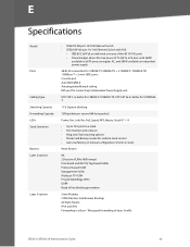
... Chain stacking options • Master and Backup master for resilient stack control • Auto-numbering or manual configuration of units in silicon - Wirespeed forwarding of line blocking prevention Static Routing CIDR (Classless Interdomain Routing) 60 Static Routes IPv4 and IPv6 Forwarding in stack Reset Button 8K 256 active VLANs (4096 range) Port-based and 802.1Q Tag-based VLANs Protocol-based VLAN Management VLAN Multicast TV VLAN Private VLAN Edge (PVE) GVRP Head of layer 3 traffic SFE2010/SFE2010P Administration Guide 60
... Chain stacking options • Master and Backup master for resilient stack control • Auto-numbering or manual configuration of units in silicon - Wirespeed forwarding of line blocking prevention Static Routing CIDR (Classless Interdomain Routing) 60 Static Routes IPv4 and IPv6 Forwarding in stack Reset Button 8K 256 active VLANs (4096 range) Port-based and 802.1Q Tag-based VLANs Protocol-based VLAN Management VLAN Multicast TV VLAN Private VLAN Edge (PVE) GVRP Head of layer 3 traffic SFE2010/SFE2010P Administration Guide 60

Administration Guide
Page 64
..., NonCondensing Built-in Web UI for easy browser-based configuration (HTTP/HTTPS) SNMP version 1, 2c, 3 with support for traps SNMP version 1, 2c, 3 with a network analyzer or RMON probe Traceroute Single IP Management Secure Socket Layer (SSL) security for enhanced traffic management, monitoring, and analysis. RADIUS Authentication. MD5 Hash Guest VLAN Single/Multiple Host mode SFE2010/SFE2010P Administration Guide 61 Environment Web User Interface SNMP SNMP MIBs RMON Firmware Upgrade Port Mirroring Other Management IEEE 802.1x Operating...
..., NonCondensing Built-in Web UI for easy browser-based configuration (HTTP/HTTPS) SNMP version 1, 2c, 3 with support for traps SNMP version 1, 2c, 3 with a network analyzer or RMON probe Traceroute Single IP Management Secure Socket Layer (SSL) security for enhanced traffic management, monitoring, and analysis. RADIUS Authentication. MD5 Hash Guest VLAN Single/Multiple Host mode SFE2010/SFE2010P Administration Guide 61 Environment Web User Interface SNMP SNMP MIBs RMON Firmware Upgrade Port Mirroring Other Management IEEE 802.1x Operating...

Administration Guide
Page 65
SFE2010/SFE2010P Administration Guide 62 Drop or Rate Limit based on: Source and Destination MAC-based Source and Destination IP address Protocol Port VLAN DSCP/IP Precedence TCP/UDP Source and Destination ports 802.1p priority Ethernet Type ICMP packets IGMP packets DHCP Snooping ARP Inspection IP Source Address Guard Up to 1018 rules Link Aggregation Link Aggregation using IEEE 802.3ad LACP Up to 8 ports in up...
SFE2010/SFE2010P Administration Guide 62 Drop or Rate Limit based on: Source and Destination MAC-based Source and Destination IP address Protocol Port VLAN DSCP/IP Precedence TCP/UDP Source and Destination ports 802.1p priority Ethernet Type ICMP packets IGMP packets DHCP Snooping ARP Inspection IP Source Address Guard Up to 1018 rules Link Aggregation Link Aggregation using IEEE 802.3ad LACP Up to 8 ports in up...


