Quick Start Guide
Page 3
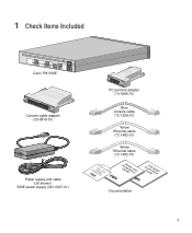
1 Check Items Included ACT LINK ETHERNET 1 ACT LINK ETHERNET 0 USB CONSOLE DC POWER INPUT Cisco PIX 506E Console cable adapter (29-0810-01) Power supply and cable (US shown) 506E power supply (341-0007-01) PC terminal adapter (74-0495-01) Blue console cable (72-1259-01) Yellow Ethernet cable (72-1482-01) ProdFuicCrteisCwcDaollPIX Yellow Ethernet cable (72-1482-01) CGoumSidapefleiatyncaend QGuuiPicdkIeXS5ta0r6tE Documentation 3
1 Check Items Included ACT LINK ETHERNET 1 ACT LINK ETHERNET 0 USB CONSOLE DC POWER INPUT Cisco PIX 506E Console cable adapter (29-0810-01) Power supply and cable (US shown) 506E power supply (341-0007-01) PC terminal adapter (74-0495-01) Blue console cable (72-1259-01) Yellow Ethernet cable (72-1482-01) ProdFuicCrteisCwcDaollPIX Yellow Ethernet cable (72-1482-01) CGoumSidapefleiatyncaend QGuuiPicdkIeXS5ta0r6tE Documentation 3
Quick Start Guide
Page 4
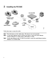
... connect the inside Ethernet interface, Ethernet 1, to a switch or hub. 4 Use the other network device Laptop computer Printer Yellow Ethernet cables Switch Cisco PIX 506E ACT ETHERNET 1 LINK ACT ETHERNET 0 LINK USB DC CONSOLE IPNOPWUETR Yellow Ethernet cable Power adapter Router Internet 71116 Follow these steps to a DSL modem, cable modem, or router. The...
... connect the inside Ethernet interface, Ethernet 1, to a switch or hub. 4 Use the other network device Laptop computer Printer Yellow Ethernet cables Switch Cisco PIX 506E ACT ETHERNET 1 LINK ACT ETHERNET 0 LINK USB DC CONSOLE IPNOPWUETR Yellow Ethernet cable Power adapter Router Internet 71116 Follow these steps to a DSL modem, cable modem, or router. The...
Quick Start Guide
Page 5
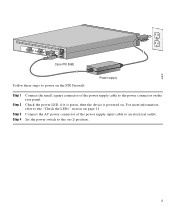
... powered on (|) position. 5 Set the power switch to the on . 67932 ACT LINK ETHERNET 1 ACT LINK ETHERNET 0 DC POWER USB CONSOLE INPUT DC POWER INPUT Cisco PIX 506E Follow these steps to power on the PIX Firewall: Power supply Step 1 Step 2 Step 3 Step 4 Connect the small, square connector of the power supply input cable to...
... powered on (|) position. 5 Set the power switch to the on . 67932 ACT LINK ETHERNET 1 ACT LINK ETHERNET 0 DC POWER USB CONSOLE INPUT DC POWER INPUT Cisco PIX 506E Follow these steps to power on the PIX Firewall: Power supply Step 1 Step 2 Step 3 Step 4 Connect the small, square connector of the power supply input cable to...
Quick Start Guide
Page 10
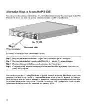
...access the CLI using the console port on a PC or workstation. 67935 ACT LINK ETHERNET 1 ACT LINK ETHERNET 0 DC POWER USB CONSOLE INPUT DC POWER INPUT Cisco PIX 506E PC terminal adapter Blue console cable To connect a console for local administrative access: Step 1 Step 2 Step 3 Step 4 ...access is not permitted. Refer to the Cisco PIX Firewall and VPN Configuration Guide for administration using SSH/Telnet to the PIX Firewall. Configure the PC terminal emulation software or terminal for a secure Telnet session. To Telnet to the PIX Firewall from the outside IP address and ...
...access the CLI using the console port on a PC or workstation. 67935 ACT LINK ETHERNET 1 ACT LINK ETHERNET 0 DC POWER USB CONSOLE INPUT DC POWER INPUT Cisco PIX 506E PC terminal adapter Blue console cable To connect a console for local administrative access: Step 1 Step 2 Step 3 Step 4 ...access is not permitted. Refer to the Cisco PIX Firewall and VPN Configuration Guide for administration using SSH/Telnet to the PIX Firewall. Configure the PC terminal emulation software or terminal for a secure Telnet session. To Telnet to the PIX Firewall from the outside IP address and ...
Quick Start Guide
Page 11
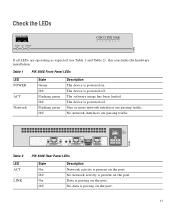
... Network State Green Off Flashing green Off Flashing green Off Description The device is present on the port. 11 Check the LEDs POWER ACT NETWORK CISCO PIX 506E F I R E WA L L 67933 If all LEDs are operating as expected (see Table 1 and Table 2), this concludes the hardware installation.... The software image has been loaded. ACT LINK ACT LINK ETHERNET 1 ETHERNET 0 USB CONSOLE DC POWER INPUT Table 2 LED ACT LINK PIX 506E Rear Panel LEDs State On Off On Off Description Network activity is powered on the port. No data is ...
... Network State Green Off Flashing green Off Flashing green Off Description The device is present on the port. 11 Check the LEDs POWER ACT NETWORK CISCO PIX 506E F I R E WA L L 67933 If all LEDs are operating as expected (see Table 1 and Table 2), this concludes the hardware installation.... The software image has been loaded. ACT LINK ACT LINK ETHERNET 1 ETHERNET 0 USB CONSOLE DC POWER INPUT Table 2 LED ACT LINK PIX 506E Rear Panel LEDs State On Off On Off Description Network activity is powered on the port. No data is ...
User Guide
Page 2
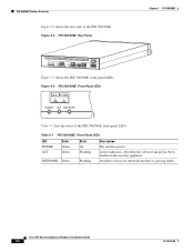
... security appliance. Figure 3-2 PIX 506/506E Rear Panel Chapter 3 PIX 506/506E 67947 ACT LINK ETHERNET 1 ACT LINK ETHERNET 0 USB CONSOLE DC POWER INPUT Figure 3-3 shows the PIX 506/506E front panel LEDs. Figure 3-3 PIX 506/506E Front Panel LEDs POWER ACT NETWORK 25735 Table 3-1 lists the states of the PIX 506/506E. On when at least one network interface is passing traffic. Cisco PIX Security Appliance...
... security appliance. Figure 3-2 PIX 506/506E Rear Panel Chapter 3 PIX 506/506E 67947 ACT LINK ETHERNET 1 ACT LINK ETHERNET 0 USB CONSOLE DC POWER INPUT Figure 3-3 shows the PIX 506/506E front panel LEDs. Figure 3-3 PIX 506/506E Front Panel LEDs POWER ACT NETWORK 25735 Table 3-1 lists the states of the PIX 506/506E. On when at least one network interface is passing traffic. Cisco PIX Security Appliance...
User Guide
Page 3
... USB port at the left of the PIX 506/506E rear panel LEDs. Chapter 3 PIX 506/506E Installing the PIX 506/506E Figure 3-4 shows the PIX 506/506E rear panel LEDs. Shows that you have either a DB-9 or DB-25 connector on one DB-25 connector. 78-15170-02 Cisco PIX Security Appliance Hardware Installation Guide 3-3 Installing the PIX 506/506E Place the PIX 506/506E on...
... USB port at the left of the PIX 506/506E rear panel LEDs. Chapter 3 PIX 506/506E Installing the PIX 506/506E Figure 3-4 shows the PIX 506/506E rear panel LEDs. Shows that you have either a DB-9 or DB-25 connector on one DB-25 connector. 78-15170-02 Cisco PIX Security Appliance Hardware Installation Guide 3-3 Installing the PIX 506/506E Place the PIX 506/506E on...
User Guide
Page 4
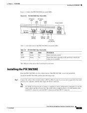
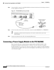
Figure 3-5 PIX 506/506E Serial Console Cable ACT LINK ETHERNET 1 ACT LINK ETHERNET 0 USB CONSOLE DC POWER INPUT Console port (RJ-45) RJ-45 to DB-9 or DB-25 serial cable (null-modem) Computer serial port DB-9 or ... PIX 506/506E. Power is supplied to the PIX 506/506E by connecting the power supply to the back of the security appliance and connecting a separate AC power cord to the interface connector marked ETHERNET 0 or ETHERNET 1. Step 4 Connect the outside network connections can be made to either interface port on your computer (see Figure 3-7). Cisco PIX Security Appliance...
Figure 3-5 PIX 506/506E Serial Console Cable ACT LINK ETHERNET 1 ACT LINK ETHERNET 0 USB CONSOLE DC POWER INPUT Console port (RJ-45) RJ-45 to DB-9 or DB-25 serial cable (null-modem) Computer serial port DB-9 or ... PIX 506/506E. Power is supplied to the PIX 506/506E by connecting the power supply to the back of the security appliance and connecting a separate AC power cord to the interface connector marked ETHERNET 0 or ETHERNET 1. Step 4 Connect the outside network connections can be made to either interface port on your computer (see Figure 3-7). Cisco PIX Security Appliance...
User Guide
Page 5
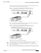
...Module to the PIX 506E 8-Pin Connector ACT LINK ETHERNET 1 ACT LINK ETHERNET 0 USB CONSOLE DC POWER INPUT 67847 Power supply Complete these steps to the back of the PIX 506/506E. Chapter 3 PIX 506/506E Connecting a Power Supply Module to the PIX 506/506E Figure 3-6 displays ...the cable connection from the power supply to the PIX 506E, and displays the AC power cord connector (at the rear of the unit. 78-15170-02 Cisco PIX Security Appliance Hardware...
...Module to the PIX 506E 8-Pin Connector ACT LINK ETHERNET 1 ACT LINK ETHERNET 0 USB CONSOLE DC POWER INPUT 67847 Power supply Complete these steps to the back of the PIX 506/506E. Chapter 3 PIX 506/506E Connecting a Power Supply Module to the PIX 506/506E Figure 3-6 displays ...the cable connection from the power supply to the PIX 506E, and displays the AC power cord connector (at the rear of the unit. 78-15170-02 Cisco PIX Security Appliance Hardware...
User Guide
Page 6
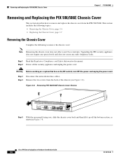
...frequency leaks. Step 3 Disconnect the network interface cables. Cisco PIX Security Appliance Hardware Installation Guide 3-6 78-15170-02 Removing and Replacing the PIX 506/506E Chassis Cover Chapter 3 PIX 506/506E Removing and Replacing the PIX 506/506E Chassis Cover This section describes how to remove the chassis ... Figure 3-8 Removing PIX 506/506E Chassis Cover Screws 119681 ACT LINK ETHERNET 1 ACT LINK ETHERNET 0 USB CONSOLE DC POWER INPUT Step 5 With the rear panel facing you, slide the chassis cover back and then lift it up off the security appliance and unplug the...
...frequency leaks. Step 3 Disconnect the network interface cables. Cisco PIX Security Appliance Hardware Installation Guide 3-6 78-15170-02 Removing and Replacing the PIX 506/506E Chassis Cover Chapter 3 PIX 506/506E Removing and Replacing the PIX 506/506E Chassis Cover This section describes how to remove the chassis ... Figure 3-8 Removing PIX 506/506E Chassis Cover Screws 119681 ACT LINK ETHERNET 1 ACT LINK ETHERNET 0 USB CONSOLE DC POWER INPUT Step 5 With the rear panel facing you, slide the chassis cover back and then lift it up off the security appliance and unplug the...