Quick Start Guide
Page 5
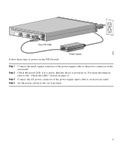
Connect the AC power connector of the power supply cable to the power connector on . For more information, refer to the "Check the LEDs" section on (|) position. 5 Set the power switch to the on page 11. Check the power LED, if it is green, then the device is powered on the rear panel. 67932 ACT LINK ETHERNET 1 ACT LINK ETHERNET 0 DC POWER USB CONSOLE INPUT DC POWER INPUT Cisco PIX 506E Follow these steps to power on the PIX Firewall: Power supply Step 1 Step 2 Step 3 Step 4 Connect the small, square connector of the power supply input cable to an electrical outlet.
Connect the AC power connector of the power supply cable to the power connector on . For more information, refer to the "Check the LEDs" section on (|) position. 5 Set the power switch to the on page 11. Check the power LED, if it is green, then the device is powered on the rear panel. 67932 ACT LINK ETHERNET 1 ACT LINK ETHERNET 0 DC POWER USB CONSOLE INPUT DC POWER INPUT Cisco PIX 506E Follow these steps to power on the PIX Firewall: Power supply Step 1 Step 2 Step 3 Step 4 Connect the small, square connector of the power supply input cable to an electrical outlet.
User Guide
Page 3
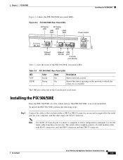
... have either a DB-9 or DB-25 connector on one DB-25 connector. 78-15170-02 Cisco PIX Security Appliance Hardware Installation Guide 3-3 The USB port at the left of the Console port is not rack mountable. Locate the serial cable from the accessory kit. Installing the PIX 506/506E Place the PIX 506/506E on the network to enter configuration...
... have either a DB-9 or DB-25 connector on one DB-25 connector. 78-15170-02 Cisco PIX Security Appliance Hardware Installation Guide 3-3 The USB port at the left of the Console port is not rack mountable. Locate the serial cable from the accessory kit. Installing the PIX 506/506E Place the PIX 506/506E on the network to enter configuration...
User Guide
Page 4
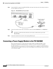
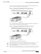
...a Power Supply Module to the PIX 506/506E Chapter 3 PIX 506/506E Step 2 Connect the RJ-45 connector to the PIX 506/506E and connect the other end to the serial port connector on the PIX 506/506E. Connecting a Power Supply Module to the PIX 506/506E This section describes how to connect... to the remaining Ethernet port. Power is supplied to the PIX 506/506E by connecting the power supply to the back of the security appliance and connecting a separate AC power cord to the PIX 506/506E. Cisco PIX Security Appliance Hardware Installation Guide 3-4 78-15170-02 Use this information in...
...a Power Supply Module to the PIX 506/506E Chapter 3 PIX 506/506E Step 2 Connect the RJ-45 connector to the PIX 506/506E and connect the other end to the serial port connector on the PIX 506/506E. Connecting a Power Supply Module to the PIX 506/506E This section describes how to connect... to the remaining Ethernet port. Power is supplied to the PIX 506/506E by connecting the power supply to the back of the security appliance and connecting a separate AC power cord to the PIX 506/506E. Cisco PIX Security Appliance Hardware Installation Guide 3-4 78-15170-02 Use this information in...
User Guide
Page 5
... the rear of the unit. 78-15170-02 Cisco PIX Security Appliance Hardware Installation Guide 3-5 See Figure 3-6 for the PIX 506 and Figure 3-7 for the PIX 506E. When you are ready to start the PIX 506/506E, power on a flat, stable surface. Figure 3-6 Connecting the Power Supply Module to the PIX 506 6-Pin Connector ACT LINK ETHERNET 1 ACT LINK ETHERNET 0 USB...
... the rear of the unit. 78-15170-02 Cisco PIX Security Appliance Hardware Installation Guide 3-5 See Figure 3-6 for the PIX 506 and Figure 3-7 for the PIX 506E. When you are ready to start the PIX 506/506E, power on a flat, stable surface. Figure 3-6 Connecting the Power Supply Module to the PIX 506 6-Pin Connector ACT LINK ETHERNET 1 ACT LINK ETHERNET 0 USB...