User Guide
Page 4
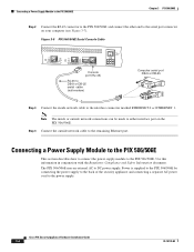
... Regulatory Compliance and Safety Information document. Power is supplied to the PIX 506/506E by connecting the power supply to the back of the security appliance and connecting a separate AC power cord to the PIX 506/506E. Connecting a Power Supply Module to the PIX 506/506E Chapter 3 PIX 506/506E Step 2 Connect the RJ-45 connector to the PIX 506/506E and connect the other end to...
... Regulatory Compliance and Safety Information document. Power is supplied to the PIX 506/506E by connecting the power supply to the back of the security appliance and connecting a separate AC power cord to the PIX 506/506E. Connecting a Power Supply Module to the PIX 506/506E Chapter 3 PIX 506/506E Step 2 Connect the RJ-45 connector to the PIX 506/506E and connect the other end to...
User Guide
Page 5
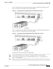
... the Power Supply Module to the PIX 506E 8-Pin Connector ACT LINK ETHERNET 1 ACT LINK ETHERNET 0 USB CONSOLE DC POWER INPUT 67847 Power supply Complete these steps to connect the power supply module: Step 1 Step 2 Step 3 Place the PIX 506/506E on the unit from the switch at the opposite end of the unit. 78-15170-02 Cisco PIX Security Appliance Hardware...
... the Power Supply Module to the PIX 506E 8-Pin Connector ACT LINK ETHERNET 1 ACT LINK ETHERNET 0 USB CONSOLE DC POWER INPUT 67847 Power supply Complete these steps to connect the power supply module: Step 1 Step 2 Step 3 Place the PIX 506/506E on the unit from the switch at the opposite end of the unit. 78-15170-02 Cisco PIX Security Appliance Hardware...
User Guide
Page 6
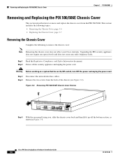
... the PIX 506/506E. Figure 3-8 Removing PIX 506/506E Chassis Cover Screws 119681 ACT LINK ETHERNET 1 ACT LINK ETHERNET 0 USB CONSOLE DC POWER INPUT Step 5 With the rear panel facing you, slide the chassis cover back and then lift it up off the security appliance and unplug the power cord. Step 1 Read the Regulatory Compliance and Safety Information document. Cisco PIX Security Appliance...
... the PIX 506/506E. Figure 3-8 Removing PIX 506/506E Chassis Cover Screws 119681 ACT LINK ETHERNET 1 ACT LINK ETHERNET 0 USB CONSOLE DC POWER INPUT Step 5 With the rear panel facing you, slide the chassis cover back and then lift it up off the security appliance and unplug the power cord. Step 1 Read the Regulatory Compliance and Safety Information document. Cisco PIX Security Appliance...
User Guide
Page 7
...the battery loses its main circuit board (see Figure 3-9). Place the PIX 506/506E on the security appliance. Reconnect the power cord and power on a flat, stable surface. Replacing a Lithium Battery The PIX 506/506E has a lithium battery on a secure surface with the bottom of the cover fit under the chassis cover... cover: Step 1 Step 2 Step 3 Step 4 Step 5 Step 6 Step 7 Step 8 Place the chassis on its charge, the PIX security appliance cannot function. Complete the following to replace the used battery. 78-15170-02 Cisco PIX Security Appliance Hardware Installation Guide 3-7
...the battery loses its main circuit board (see Figure 3-9). Place the PIX 506/506E on the security appliance. Reconnect the power cord and power on a flat, stable surface. Replacing a Lithium Battery The PIX 506/506E has a lithium battery on a secure surface with the bottom of the cover fit under the chassis cover... cover: Step 1 Step 2 Step 3 Step 4 Step 5 Step 6 Step 7 Step 8 Place the chassis on its charge, the PIX security appliance cannot function. Complete the following to replace the used battery. 78-15170-02 Cisco PIX Security Appliance Hardware Installation Guide 3-7
