Quick Start Guide
Page 5
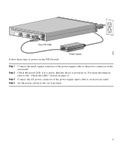
67932 ACT LINK ETHERNET 1 ACT LINK ETHERNET 0 DC POWER USB CONSOLE INPUT DC POWER INPUT Cisco PIX 506E Follow these steps to power on the PIX Firewall: Power supply Step 1 Step 2 Step 3 Step 4 Connect the small, square connector of the power supply input cable to an electrical outlet. Set the power switch to the "Check the... the on page 11. Check the power LED, if it is green, then the device is powered on the rear panel. Connect the AC power connector of the power supply cable to the power...
67932 ACT LINK ETHERNET 1 ACT LINK ETHERNET 0 DC POWER USB CONSOLE INPUT DC POWER INPUT Cisco PIX 506E Follow these steps to power on the PIX Firewall: Power supply Step 1 Step 2 Step 3 Step 4 Connect the small, square connector of the power supply input cable to an electrical outlet. Set the power switch to the "Check the... the on page 11. Check the power LED, if it is green, then the device is powered on the rear panel. Connect the AC power connector of the power supply cable to the power...
User Guide
Page 3
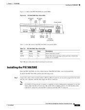
... configuration commands. Locate the serial cable from the accessory kit. The serial cable assembly consists of the PIX 506/506E rear panel LEDs. Installing the PIX 506/506E Place the PIX 506/506E on one DB-25 connector. 78-15170-02 Cisco PIX Security Appliance Hardware Installation Guide 3-3 Note Use the RJ-45 Console port to connect a computer to which the...
... configuration commands. Locate the serial cable from the accessory kit. The serial cable assembly consists of the PIX 506/506E rear panel LEDs. Installing the PIX 506/506E Place the PIX 506/506E on one DB-25 connector. 78-15170-02 Cisco PIX Security Appliance Hardware Installation Guide 3-3 Note Use the RJ-45 Console port to connect a computer to which the...
User Guide
Page 4
... to the PIX 506/506E by connecting the power supply to the back of the security appliance and connecting a separate AC power cord to the remaining Ethernet port. Note The inside network cable to the interface connector marked ETHERNET 0 or ETHERNET 1. Use this information in conjunction with the Regulatory Compliance and Safety Information document. Cisco PIX Security Appliance Hardware...
... to the PIX 506/506E by connecting the power supply to the back of the security appliance and connecting a separate AC power cord to the remaining Ethernet port. Note The inside network cable to the interface connector marked ETHERNET 0 or ETHERNET 1. Use this information in conjunction with the Regulatory Compliance and Safety Information document. Cisco PIX Security Appliance Hardware...
User Guide
Page 5
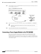
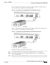
... unit from the power supply to the PIX 506, and displays the AC power cord connector (at the rear of the unit. 78-15170-02 Cisco PIX Security Appliance Hardware Installation Guide 3-5 See Figure 3-6 for the PIX 506 and Figure 3-7 for the PIX 506E. Figure 3-7 Connecting the Power Supply Module to the PIX 506E 8-Pin Connector ACT LINK ETHERNET 1 ACT LINK ETHERNET...
... unit from the power supply to the PIX 506, and displays the AC power cord connector (at the rear of the unit. 78-15170-02 Cisco PIX Security Appliance Hardware Installation Guide 3-5 See Figure 3-6 for the PIX 506 and Figure 3-7 for the PIX 506E. Figure 3-7 Connecting the Power Supply Module to the PIX 506E 8-Pin Connector ACT LINK ETHERNET 1 ACT LINK ETHERNET...