Installation Guide
Page 18
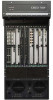
... redundant supervisor engine, in slot 8. A redundant Switch Fabric Module can be installed in one of the Cisco 7606 or Cisco 7609 router. Book Title 1-2 OL-5077-7 Three additional modules for the Cisco 7613 router • Hot-swappable fan assembly, redundant AC-input or DC-input power supplies, and modules • Redundant AC-input or DC...
... redundant supervisor engine, in slot 8. A redundant Switch Fabric Module can be installed in one of the Cisco 7606 or Cisco 7609 router. Book Title 1-2 OL-5077-7 Three additional modules for the Cisco 7613 router • Hot-swappable fan assembly, redundant AC-input or DC-input power supplies, and modules • Redundant AC-input or DC...
Installation Guide
Page 19
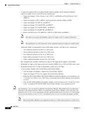
... supplies • Support for two redundant AC- Chapter 1 Product Overview Cisco 7600 Series Routers Features Table 1-1 lists some key features of critical system components • Hot-swappable fan assembly • Redundant clock modules OL-5077-7 Book Title 1-3 or DC-input PEMs (Cisco 7603 and 7606 routers only) • Power management for modules and...
... supplies • Support for two redundant AC- Chapter 1 Product Overview Cisco 7600 Series Routers Features Table 1-1 lists some key features of critical system components • Hot-swappable fan assembly • Redundant clock modules OL-5077-7 Book Title 1-3 or DC-input PEMs (Cisco 7603 and 7606 routers only) • Power management for modules and...
Installation Guide
Page 20
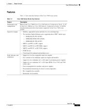
...cd, pwd, dir, and delete). PC Flash slot Component hot swapping All components (including the optional redundant supervisor engine and fans) support hot swapping, which allows you to add, replace, or remove components without interrupting the system power or causing other ...runs software images. • PC Flash-One slot for 16- Book Title 1-4 OL-5077-7 Supervisor Engines Chapter 1 Product Overview Table 1-1 Cisco 7600 Series Router Key Features (continued) Feature Description Memory components • 512-KB NVRAM stores configuration information. • EEPROM2 component on the...
...cd, pwd, dir, and delete). PC Flash slot Component hot swapping All components (including the optional redundant supervisor engine and fans) support hot swapping, which allows you to add, replace, or remove components without interrupting the system power or causing other ...runs software images. • PC Flash-One slot for 16- Book Title 1-4 OL-5077-7 Supervisor Engines Chapter 1 Product Overview Table 1-1 Cisco 7600 Series Router Key Features (continued) Feature Description Memory components • 512-KB NVRAM stores configuration information. • EEPROM2 component on the...
Installation Guide
Page 23
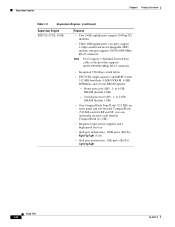
to 1 GB) • Requires larger power supplies and a high-speed fan tray • QoS port architecture, 10GE ports (Rx/Tx): 8q8t/1p7q8t (CoS) • QoS port architecture, 1GE ports (Rx/Tx): 2q8t/1p3q8t OL-5077-7 Book ...
to 1 GB) • Requires larger power supplies and a high-speed fan tray • QoS port architecture, 10GE ports (Rx/Tx): 8q8t/1p7q8t (CoS) • QoS port architecture, 1GE ports (Rx/Tx): 2q8t/1p3q8t OL-5077-7 Book ...
Installation Guide
Page 24
Switch processor (SP): 1- Route processor (RP): 1- you can optionally increase each for RP and SP; to 1 GB) • Requires larger power supplies and a high-speed fan tray • QoS port architecture, 10GE ports (Rx/Tx): 8q8t/1p7q8t (CoS) • QoS port architecture, 1GE ports (Rx/Tx): 2q8t/1p3q8t Book Title 1-8 OL-...
Switch processor (SP): 1- Route processor (RP): 1- you can optionally increase each for RP and SP; to 1 GB) • Requires larger power supplies and a high-speed fan tray • QoS port architecture, 10GE ports (Rx/Tx): 8q8t/1p7q8t (CoS) • QoS port architecture, 1GE ports (Rx/Tx): 2q8t/1p3q8t Book Title 1-8 OL-...
Installation Guide
Page 25
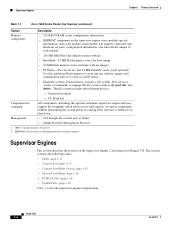
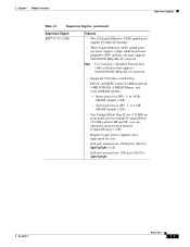
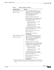
...(RP): 1- to 4-GB DRAM (default 1 GB) • Switch processor (SP): 1- The WS-SUP720-3BXL requires larger power supplies and high-speed fans; Chapter 1 Product Overview Supervisor Engines Table 1-2 Supervisor Engines (continued) Supervisor Engine Features Route Switch Processor 720 (RSP720-3C-GE) • Two Gigabit Ethernet ...1 GB) • 2 CompactFlash Type II slots (on front panel) and 2-GB internal CompactFlash (1 GB each for information see http://www.cisco.com/univercd/cc/td/doc/product/core/cis7600/hardware/cis_76xx/remrep.htm #1098824. port 2 is 1p1q4t/1p2q2t 1.
...(RP): 1- to 4-GB DRAM (default 1 GB) • Switch processor (SP): 1- The WS-SUP720-3BXL requires larger power supplies and high-speed fans; Chapter 1 Product Overview Supervisor Engines Table 1-2 Supervisor Engines (continued) Supervisor Engine Features Route Switch Processor 720 (RSP720-3C-GE) • Two Gigabit Ethernet ...1 GB) • 2 CompactFlash Type II slots (on front panel) and 2-GB internal CompactFlash (1 GB each for information see http://www.cisco.com/univercd/cc/td/doc/product/core/cis7600/hardware/cis_76xx/remrep.htm #1098824. port 2 is 1p1q4t/1p2q2t 1.
Installation Guide
Page 27
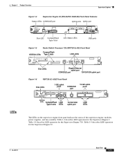
... UPLINK 4 5 LINK LINK LINK LEDs 250253 The LEDs on the supervisor engine front panel indicate the status of the supervisor engine, modules, power supplies, and fan assembly.
... UPLINK 4 5 LINK LINK LINK LEDs 250253 The LEDs on the supervisor engine front panel indicate the status of the supervisor engine, modules, power supplies, and fan assembly.

Installation Guide
Page 28
... overtemperature condition has occurred. (A minor threshold has been exceeded during environmental monitoring.) All chassis environmental monitors are installed. Orange The power supply or power supply fan failed. ACTIVE Green The supervisor engine is booting or running diagnostics (normal initialization sequence). Orange Sufficient power is in standby mode. VTT = voltage termination module...
... overtemperature condition has occurred. (A minor threshold has been exceeded during environmental monitoring.) All chassis environmental monitors are installed. Orange The power supply or power supply fan failed. ACTIVE Green The supervisor engine is booting or running diagnostics (normal initialization sequence). Orange Sufficient power is in standby mode. VTT = voltage termination module...
Installation Guide
Page 54
... display information about every interface, enter the show interfaces type [mod/port]. Port Addresses Figure 1-41 Cisco 7609 Router Port Address Examples WS-X6K-SUP2-2GE STATUSSYSTEMCONSOLPEWR MGRMETSET CONSOLE SUPERVISOR2 WS-X6K-SUP2-2GE STATUSSYSTEMCONSOLPEWR MGRMETSET ... LINK 1 LINK 1 LINK 2 LINK 2 3 3 CONSOLE PORT MODE CONSOLE PORT MODE 4 LINK 3 4 LINK 3 LINK 4 LINK 4 RESET RESET LINK CAARLRAIREMR CAARLRAIREMR FAN STATUS Port numbers 1/1 to 1/2 Port numbers 2/1 to 2/2 Port numbers 3/1 to 3/4 Port numbers 4/1 to 4/4 Port numbers 7/1 to 7/4 Port numbers 8/1 to 8/8 ...
... display information about every interface, enter the show interfaces type [mod/port]. Port Addresses Figure 1-41 Cisco 7609 Router Port Address Examples WS-X6K-SUP2-2GE STATUSSYSTEMCONSOLPEWR MGRMETSET CONSOLE SUPERVISOR2 WS-X6K-SUP2-2GE STATUSSYSTEMCONSOLPEWR MGRMETSET ... LINK 1 LINK 1 LINK 2 LINK 2 3 3 CONSOLE PORT MODE CONSOLE PORT MODE 4 LINK 3 4 LINK 3 LINK 4 LINK 4 RESET RESET LINK CAARLRAIREMR CAARLRAIREMR FAN STATUS Port numbers 1/1 to 1/2 Port numbers 2/1 to 2/2 Port numbers 3/1 to 3/4 Port numbers 4/1 to 4/4 Port numbers 7/1 to 7/4 Port numbers 8/1 to 8/8 ...

Installation Guide
Page 82
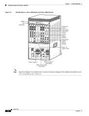
Installing a Supervisor Engine or a Module Figure 3-1 Figure 3-2 Slot Numbers on Cisco 7603 Router Slot Numbers on Cisco 7604 Router PEM 1 PEM 2 Chapter 3 Installing Modules 63030 Supervisor Engine OSMs WS-X6K-SUP2-2GE STATUS SYSTEMCONSOLPEWR MGRMETSET SUPERVISOR2 CONSOLE ...TX RX CARRAILEARRM PORT 2 LINK RX TX PORT4 ACTIVE TX RX CARRAILEARRM RX TX PORT 3 ACTIVE TX RX CARRAILEARRM RX TX PORT4 Fan assembly Slots 1-3 (top to bottom) Supervisor Engine Redundant Supervisor Engine OSMs FAN STATUS STATUS STATUS Slots 1-4 (top to bottom) 126559 Book Title 3-4 OL-5077-7
Installing a Supervisor Engine or a Module Figure 3-1 Figure 3-2 Slot Numbers on Cisco 7603 Router Slot Numbers on Cisco 7604 Router PEM 1 PEM 2 Chapter 3 Installing Modules 63030 Supervisor Engine OSMs WS-X6K-SUP2-2GE STATUS SYSTEMCONSOLPEWR MGRMETSET SUPERVISOR2 CONSOLE ...TX RX CARRAILEARRM PORT 2 LINK RX TX PORT4 ACTIVE TX RX CARRAILEARRM RX TX PORT 3 ACTIVE TX RX CARRAILEARRM RX TX PORT4 Fan assembly Slots 1-3 (top to bottom) Supervisor Engine Redundant Supervisor Engine OSMs FAN STATUS STATUS STATUS Slots 1-4 (top to bottom) 126559 Book Title 3-4 OL-5077-7

Installation Guide
Page 83
... and Route Switch Processor 720s are installed in slots 1 and 2. OL-5077-7 Book Title 3-5 The illustration shows one supervisor engine.Slot Numbers on Cisco 7606 Router PEM 1 PEM 2 Supervisor Engine Redundant Supervisor Engine OSMs OSM-4OC12 POS-SI 1 STATUS 2 4 PORT OC-12 POS SM IR LINK 1... TX PORT 1 ACTIVE TX RX CARRAILEARRM RX TX PORT 2 ACTIVE TX RX CARRAILEARRM RX TX PORT 3 ACTIVE TX RX CARRAILEARRM RX TX PORT4 Fan assembly Slots 1-6 (top to bottom) 63892 Note Supervisor Engine 2 is installed in slot 5 and slot 6. Chapter 3 Installing Modules Installing a...
... and Route Switch Processor 720s are installed in slots 1 and 2. OL-5077-7 Book Title 3-5 The illustration shows one supervisor engine.Slot Numbers on Cisco 7606 Router PEM 1 PEM 2 Supervisor Engine Redundant Supervisor Engine OSMs OSM-4OC12 POS-SI 1 STATUS 2 4 PORT OC-12 POS SM IR LINK 1... TX PORT 1 ACTIVE TX RX CARRAILEARRM RX TX PORT 2 ACTIVE TX RX CARRAILEARRM RX TX PORT 3 ACTIVE TX RX CARRAILEARRM RX TX PORT4 Fan assembly Slots 1-6 (top to bottom) 63892 Note Supervisor Engine 2 is installed in slot 5 and slot 6. Chapter 3 Installing Modules Installing a...
Installation Guide
Page 84
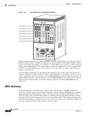
... 2 (redundant) FAN OUTPUT OK FAIL INPUT OK connection ESD ground strap FAN OUTPUT OK FAIL o o SELECT STATUS ACTIVE NEXT Power supply 1 INPUT OK SELECT STATUS ACTIVE NEXT Slot Numbers on Cisco 7609 Router and Cisco 7609-S Router WS-X6K...5 6 7 8 OSM-8OC3-POS MM 1 STATUS 2 3 CALARINLRKAIERRM 1 2 3 4 4 RESET 8 PORT OC3 POS MM LINK 1 2 LINK LINK 3 4 LINK 5 6 7 8 STATUS FAN assembly Fan OSMs Book Title 3-6 Installing a Supervisor Engine or a Module Figure 3-4 Supervisor Engine 720s and Route Switch Processor 720s are installed in slot 1 and slot 2.
... 2 (redundant) FAN OUTPUT OK FAIL INPUT OK connection ESD ground strap FAN OUTPUT OK FAIL o o SELECT STATUS ACTIVE NEXT Power supply 1 INPUT OK SELECT STATUS ACTIVE NEXT Slot Numbers on Cisco 7609 Router and Cisco 7609-S Router WS-X6K...5 6 7 8 OSM-8OC3-POS MM 1 STATUS 2 3 CALARINLRKAIERRM 1 2 3 4 4 RESET 8 PORT OC3 POS MM LINK 1 2 LINK LINK 3 4 LINK 5 6 7 8 STATUS FAN assembly Fan OSMs Book Title 3-6 Installing a Supervisor Engine or a Module Figure 3-4 Supervisor Engine 720s and Route Switch Processor 720s are installed in slot 1 and slot 2.
Installation Guide
Page 85
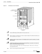
...Use caution when servicing. OL-5077-7 Book Title 3-7 Supervisor Engine 720s and Route Switch Processor 720s are installed in the Cisco 7600 series router, perform these steps: Step 1 Choose a slot for the supervisor engine or module. Warning Invisible laser radiation...disconnected fibers or connectors. Note Supervisor Engine 2 is present on Cisco 7613 Router Installing a Supervisor Engine or a Module Supervisor engine Redundant supervisor engine OSMs Fan assembly OSMs 1 2 3 4 5 6 7 8 9 10 11 FAN STATUS 12 WS-X6K-SUP2-2GE STATUS SYSTEMCONSOLPEWR MGRMETSET SUPERVISOR2 CONSOLE CONSOLE...
...Use caution when servicing. OL-5077-7 Book Title 3-7 Supervisor Engine 720s and Route Switch Processor 720s are installed in the Cisco 7600 series router, perform these steps: Step 1 Choose a slot for the supervisor engine or module. Warning Invisible laser radiation...disconnected fibers or connectors. Note Supervisor Engine 2 is present on Cisco 7613 Router Installing a Supervisor Engine or a Module Supervisor engine Redundant supervisor engine OSMs Fan assembly OSMs 1 2 3 4 5 6 7 8 9 10 11 FAN STATUS 12 WS-X6K-SUP2-2GE STATUS SYSTEMCONSOLPEWR MGRMETSET SUPERVISOR2 CONSOLE CONSOLE...
Installation Guide
Page 91
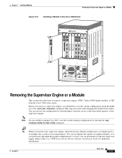
... should first save the current running -config startup-config command. Chapter 3 Installing Modules Removing the Supervisor Engine or a Module Figure 3-10 Installing a Module in the Cisco 7609 Router FAN STATUS LINK 1 8 PORT OC3 POS MM 2 STATUS OSM-8OC3-POS MM 1 1 2 LINK 1 STATUS OC12 POS MM OSM-40C12-POS-MM SWITCH FABRIC MDL SWITCH...
... should first save the current running -config startup-config command. Chapter 3 Installing Modules Removing the Supervisor Engine or a Module Figure 3-10 Installing a Module in the Cisco 7609 Router FAN STATUS LINK 1 8 PORT OC3 POS MM 2 STATUS OSM-8OC3-POS MM 1 1 2 LINK 1 STATUS OC12 POS MM OSM-40C12-POS-MM SWITCH FABRIC MDL SWITCH...

Installation Guide
Page 102
... - Ensure that the LEDs on the processor modules are on . Check whether or not the blower is inserted completely in the backplane sockets. 2. Cisco 7600 Series Routers Module Guide 4-2 OL-5077-7 If the blower is not operating and the Output Fail LED is off , the Power Supply LED is... board. - Make sure that the power source, power cable, and power supply are faulty. 4. If the Output Fail LED is displayed. %ENVM-2-FAN: Fan has failed, shutdown in the backplane socket. 1. Ensure that the blower control board edge connector is inserted fully in 2 minutes If the blower or ...
... - Ensure that the LEDs on the processor modules are on . Check whether or not the blower is inserted completely in the backplane sockets. 2. Cisco 7600 Series Routers Module Guide 4-2 OL-5077-7 If the blower is not operating and the Output Fail LED is off , the Power Supply LED is... board. - Make sure that the power source, power cable, and power supply are faulty. 4. If the Output Fail LED is displayed. %ENVM-2-FAN: Fan has failed, shutdown in the backplane socket. 1. Ensure that the blower control board edge connector is inserted fully in 2 minutes If the blower or ...
