Installation Guide
Page 2
... and NPE-G2 contain an I /O controller. Note If you are upgrading to the NPE-G1 or NPE-G2. See the "Boot Changes in existing I/O controllers. You therefore must make the existing Cisco IOS software image and configuration files available to the NPE-G1 or NPE-G2, either by putting these interfaces to perform the following procedure only if you are upgrading to an NPE-G2 from an NPE-400 or earlier network processing engine. Network Processing Engine and Network Services Engine Installation and Configuration...
... and NPE-G2 contain an I /O controller. Note If you are upgrading to the NPE-G1 or NPE-G2. See the "Boot Changes in existing I/O controllers. You therefore must make the existing Cisco IOS software image and configuration files available to the NPE-G1 or NPE-G2, either by putting these interfaces to perform the following procedure only if you are upgrading to an NPE-G2 from an NPE-400 or earlier network processing engine. Network Processing Engine and Network Services Engine Installation and Configuration...
Installation Guide
Page 3
... you install the NPE-G1 or NPE-G2. Step 4 (Optional) Copy the proper Cisco IOS software image (see Table 8-4 on removing the existing I /O controller and copy the configuration file to a Type 2 Flash Disk using the format command. OL-4448-12 Network Processing Engine and Network Services Engine Installation and Configuration 7-3 Chapter 7 NPE-G1 and NPE-G2 Installation and Configuration Information Preparing for an Upgrade Before you install an NPE-G1 or NPE-G2 in an existing router and remove the existing processor and I/O controller, do not need to...
... you install the NPE-G1 or NPE-G2. Step 4 (Optional) Copy the proper Cisco IOS software image (see Table 8-4 on removing the existing I /O controller and copy the configuration file to a Type 2 Flash Disk using the format command. OL-4448-12 Network Processing Engine and Network Services Engine Installation and Configuration 7-3 Chapter 7 NPE-G1 and NPE-G2 Installation and Configuration Information Preparing for an Upgrade Before you install an NPE-G1 or NPE-G2 in an existing router and remove the existing processor and I/O controller, do not need to...
Installation Guide
Page 4
... or NPE-G2 NVRAM for copying it . Continue? [confirm] Format :Drive communication and 1st Sector Write OK... If slot 0 is full, use slot0 or slot1 as part of disk0:complete The Flash Disk is present. Writing Monlib sectors Monlib write complete Format:All system sectors written. Network Processing Engine and Network Services Engine Installation and Configuration 7-4 OL-4448-12 If you formatted it manually using a PC card, use slot 1. Cisco...
... or NPE-G2 NVRAM for copying it . Continue? [confirm] Format :Drive communication and 1st Sector Write OK... If slot 0 is full, use slot0 or slot1 as part of disk0:complete The Flash Disk is present. Writing Monlib sectors Monlib write complete Format:All system sectors written. Network Processing Engine and Network Services Engine Installation and Configuration 7-4 OL-4448-12 If you formatted it manually using a PC card, use slot 1. Cisco...
Installation Guide
Page 5
... instructions on removing the current network processing engine or network services engine and replacing it with the NPE-G1 or NPE-G2. Go to display the router's running -config command to the "Removing the Network Processing Engine" section on page 7-7 for a pound sign [#]). Enter the show running -config command. If you have a Flash Disk 0 or 1, use slot0 or slot1 as part of the command. To copy the running configuration file to the Flash Disk or PC Card, enter the copy running-config...
... instructions on removing the current network processing engine or network services engine and replacing it with the NPE-G1 or NPE-G2. Go to display the router's running -config command to the "Removing the Network Processing Engine" section on page 7-7 for a pound sign [#]). Enter the show running -config command. If you have a Flash Disk 0 or 1, use slot0 or slot1 as part of the command. To copy the running configuration file to the Flash Disk or PC Card, enter the copy running-config...
Installation Guide
Page 7
...listed in privileged EXEC mode to the router's console port. Note Refer to a text file. Removing the Network Processing Engine Before you are installing a Port Adapter Jacket Card, see the Port Adapter Jacket Card Installation Guide for specific configuration instructions. Step 1 Step 2 Step 3 Connect a serial port on the PC and configure it for the same baud rate, parity, and stop-bits that it , you must install an I/O controller blank panel (Cisco Product Number IO-CONTROLR-BLANK=) in this chapter for removal of an existing network processing engine or network services engine...
...listed in privileged EXEC mode to the router's console port. Note Refer to a text file. Removing the Network Processing Engine Before you are installing a Port Adapter Jacket Card, see the Port Adapter Jacket Card Installation Guide for specific configuration instructions. Step 1 Step 2 Step 3 Connect a serial port on the PC and configure it for the same baud rate, parity, and stop-bits that it , you must install an I/O controller blank panel (Cisco Product Number IO-CONTROLR-BLANK=) in this chapter for removal of an existing network processing engine or network services engine...
Installation Guide
Page 8
... router. Step 1 Facing the rear of the router, place the power switch on page 7-4. Removing the Network Processing Engine Chapter 7 NPE-G1 and NPE-G2 Installation and Configuration Information Ensuring Easy Access to the Router If your Cisco 7200 VXR router or Cisco uBR7200 series router is installed in a standard 19-inch, 4-post or telco-type rack, cables from other equipment in the rack might have more than one other person is available to support...
... router. Step 1 Facing the rear of the router, place the power switch on page 7-4. Removing the Network Processing Engine Chapter 7 NPE-G1 and NPE-G2 Installation and Configuration Information Ensuring Easy Access to the Router If your Cisco 7200 VXR router or Cisco uBR7200 series router is installed in a standard 19-inch, 4-post or telco-type rack, cables from other equipment in the rack might have more than one other person is available to support...
Installation Guide
Page 9
... power supply turns off. • The fans stop operating. • The LEDs on the I/O controller turn off. • The LEDs on the port adapters turn off. Wait at least 90 seconds before powering it on again. Step 2 Observe the following steps: Step 1 Step 2 Step 3 Unplug the input power cable from the power supply. Chapter 7 NPE-G1 and NPE-G2 Installation and Configuration Information Removing the Network Processing Engine Note When powering off the router, wait a minimum of the input power cable from the power...
... power supply turns off. • The fans stop operating. • The LEDs on the I/O controller turn off. • The LEDs on the port adapters turn off. Wait at least 90 seconds before powering it on again. Step 2 Observe the following steps: Step 1 Step 2 Step 3 Unplug the input power cable from the power supply. Chapter 7 NPE-G1 and NPE-G2 Installation and Configuration Information Removing the Network Processing Engine Note When powering off the router, wait a minimum of the input power cable from the power...

Installation Guide
Page 13
... to the power supply faceplate. Chapter 7 NPE-G1 and NPE-G2 Installation and Configuration Information Removing the Network Processing Engine Step 5 Repeat this step for disconnecting DC-input power from a Cisco 7200 VXR router. This completes the procedure for the -V lead and the ground lead. OL-4448-12 Network Processing Engine and Network Services Engine Installation and Configuration 7-13 Typically, green or green and yellow are used for the DC-input power supply matches the lead color coding used at your...
... to the power supply faceplate. Chapter 7 NPE-G1 and NPE-G2 Installation and Configuration Information Removing the Network Processing Engine Step 5 Repeat this step for disconnecting DC-input power from a Cisco 7200 VXR router. This completes the procedure for the -V lead and the ground lead. OL-4448-12 Network Processing Engine and Network Services Engine Installation and Configuration 7-13 Typically, green or green and yellow are used for the DC-input power supply matches the lead color coding used at your...
Installation Guide
Page 16
... a bottom-to remove the network processing engine. Note The weight of the network processing engine. (See Figure 7-6.) If the router is rack-mounted, remove the port adapters, network processing engine and I /O controller in your Cisco 7200 VXR or Cisco uBR7246VXR router might make it difficult to -top order. See the "Removing and Replacing an AC-Input or DC-Input Power Supply" section on page 10-14 for information on the faceplate of installed power supplies in the lowest...
... a bottom-to remove the network processing engine. Note The weight of the network processing engine. (See Figure 7-6.) If the router is rack-mounted, remove the port adapters, network processing engine and I /O controller in your Cisco 7200 VXR or Cisco uBR7246VXR router might make it difficult to -top order. See the "Removing and Replacing an AC-Input or DC-Input Power Supply" section on page 10-14 for information on the faceplate of installed power supplies in the lowest...
Installation Guide
Page 18
... power cable is rack-mounted, remove the port adapters, network processing engine and I/O controller from the chassis and reinstall them , in a bottom-to-top order. Use the following procedures: • Basic Guidelines, page 7-18 • Installing a CompactFlash Disk, page 7-19 • Installing a USB Flash Memory Module or eToken-NPE-G2, page 7-19 • Installing an SFP Module-NPE-G2, page 7-20 • Installing a GBIC-NPE-G1, page 7-23 • Replacing the DIMM on the NPE-G2, page 7-24 • Upgrading...
... power cable is rack-mounted, remove the port adapters, network processing engine and I/O controller from the chassis and reinstall them , in a bottom-to-top order. Use the following procedures: • Basic Guidelines, page 7-18 • Installing a CompactFlash Disk, page 7-19 • Installing a USB Flash Memory Module or eToken-NPE-G2, page 7-19 • Installing an SFP Module-NPE-G2, page 7-20 • Installing a GBIC-NPE-G1, page 7-23 • Replacing the DIMM on the NPE-G2, page 7-24 • Upgrading...

Installation Guide
Page 20
...or NPE-G2 Chapter 7 NPE-G1 and NPE-G2 Installation and Configuration Information Caution Do not remove a USB Flash memory module when a read or write operation to a Router USB Port FE LINK U S AUX B FOR FE 0/2 UMSAENOAGNELYMENT USB 138993 Note For detailed information about the Cisco IOS commands that support USB Flash memory modules, see the Cisco USB eToken and USB Flash Features Support document. Figure 7-8 Connecting a USB Flash Memory Module to the USB Flash memory module is a separately orderable part and ships installed in your NPE-G2. However, if you connect the cables...
...or NPE-G2 Chapter 7 NPE-G1 and NPE-G2 Installation and Configuration Information Caution Do not remove a USB Flash memory module when a read or write operation to a Router USB Port FE LINK U S AUX B FOR FE 0/2 UMSAENOAGNELYMENT USB 138993 Note For detailed information about the Cisco IOS commands that support USB Flash memory modules, see the Cisco USB eToken and USB Flash Features Support document. Figure 7-8 Connecting a USB Flash Memory Module to the USB Flash memory module is a separately orderable part and ships installed in your NPE-G2. However, if you connect the cables...
Installation Guide
Page 22
... fiber connections before connecting optical cables to install the network interface optical fiber cable. Note The SFP module is on inserting the NPE-G2 into the chassis, see the Inspection and Cleaning Procedures for Fiber-Optic Connections document and the Compressed Air Cleaning Issues for future use. Installing the NPE-G1 or NPE-G2 Chapter 7 NPE-G1 and NPE-G2 Installation and Configuration Information Figure 7-10 Inserting an SFP Module into SFP port 0/1, 0/2, or...
... fiber connections before connecting optical cables to install the network interface optical fiber cable. Note The SFP module is on inserting the NPE-G2 into the chassis, see the Inspection and Cleaning Procedures for Fiber-Optic Connections document and the Compressed Air Cleaning Issues for future use. Installing the NPE-G1 or NPE-G2 Chapter 7 NPE-G1 and NPE-G2 Installation and Configuration Information Figure 7-10 Inserting an SFP Module into SFP port 0/1, 0/2, or...

Installation Guide
Page 29
... NPE-G2 must be fastened to allow the cable-management bracket to the front mounting strips of cable-management brackets. The NPE-G1- Figure 7-17 illustrates installing the bracket on the NPE-G1 or NPE-G2 on the Cisco uBR7200 series routers. Note The captive installation screws on page 10-14 when replacing a power supply in the rack, install the cable-management brackets to use the following instructions. OL-4448-12 Network Processing Engine and Network Services Engine Installation and Configuration 7-29 One type...
... NPE-G2 must be fastened to allow the cable-management bracket to the front mounting strips of cable-management brackets. The NPE-G1- Figure 7-17 illustrates installing the bracket on the NPE-G1 or NPE-G2 on the Cisco uBR7200 series routers. Note The captive installation screws on page 10-14 when replacing a power supply in the rack, install the cable-management brackets to use the following instructions. OL-4448-12 Network Processing Engine and Network Services Engine Installation and Configuration 7-29 One type...
Installation Guide
Page 45
... the port adapters or I/O controller or NPE-G1 or NPE-G2 interfaces. - Each port adapter is inserted in its slot, and its respective captive installation screws are connected to the on a Cisco uBR7200 series power supply is turned to the power supply faceplate with the cable-retention clip, except for 90 seconds. For a Cisco uBR7246VXR router, each DC lead is turned on . The console terminal is connected and secured to the off (O) position, the power supply enters a reset cycle...
... the port adapters or I/O controller or NPE-G1 or NPE-G2 interfaces. - Each port adapter is inserted in its slot, and its respective captive installation screws are connected to the on a Cisco uBR7200 series power supply is turned to the power supply faceplate with the cable-retention clip, except for 90 seconds. For a Cisco uBR7246VXR router, each DC lead is turned on . The console terminal is connected and secured to the off (O) position, the power supply enters a reset cycle...
Installation Guide
Page 48
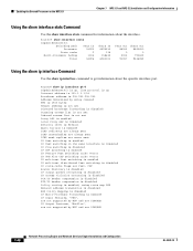
....255 Address determined by setup command MTU is 1500 bytes Helper address is not set Directed broadcast forwarding is disabled Outgoing access list is not set Inbound access list is not set Proxy ARP is enabled Local Proxy ARP is disabled Security level is default Split horizon is enabled IP fast switching on the NPE-G1 Chapter 7 NPE-G1 and NPE-G2 Installation and Configuration Information Using the show interface stats Command Use the show interface stats command for information about the specific interface port. Router# show ip interface command to...
....255 Address determined by setup command MTU is 1500 bytes Helper address is not set Directed broadcast forwarding is disabled Outgoing access list is not set Inbound access list is not set Proxy ARP is enabled Local Proxy ARP is disabled Security level is default Split horizon is enabled IP fast switching on the NPE-G1 Chapter 7 NPE-G1 and NPE-G2 Installation and Configuration Information Using the show interface stats Command Use the show interface stats command for information about the specific interface port. Router# show ip interface command to...
Installation Guide
Page 52
... and is not a supported configuration. The set of PA-2FE, PA-POS-2OC3, and I /O controller from the router, and you have not been able to copy the file to a CompactFlash Disk, use the procedure given in the "Downloading the Saved Configuration from power-on the NPE-G1 or NPE-G2. • If you have removed the previously installed I /O-2FE qualify for c7200 bandwidth points oversubscription/usage guidelines...
... and is not a supported configuration. The set of PA-2FE, PA-POS-2OC3, and I /O controller from the router, and you have not been able to copy the file to a CompactFlash Disk, use the procedure given in the "Downloading the Saved Configuration from power-on the NPE-G1 or NPE-G2. • If you have removed the previously installed I /O-2FE qualify for c7200 bandwidth points oversubscription/usage guidelines...
Installation Guide
Page 57
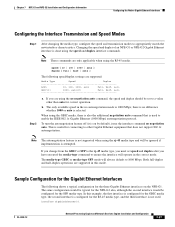
... the rj-45 media type, you have executed the media-type command to enable the IEEE 802.1z Gigabit Ethernet (1000 Mbps) autonegotiation protocol. The media-type GBIC or media-type SFP mode will be set speed and duplex after you must set to 1000 Mbps. interface GigabitEthernet0/1 OL-4448-12 Network Processing Engine and Network Services Engine Installation and Configuration 7-57 Note These commands are supported: Media Type Speed Duplex RJ45 10, 100...
... the rj-45 media type, you have executed the media-type command to enable the IEEE 802.1z Gigabit Ethernet (1000 Mbps) autonegotiation protocol. The media-type GBIC or media-type SFP mode will be set speed and duplex after you must set to 1000 Mbps. interface GigabitEthernet0/1 OL-4448-12 Network Processing Engine and Network Services Engine Installation and Configuration 7-57 Note These commands are supported: Media Type Speed Duplex RJ45 10, 100...
Installation Guide
Page 59
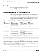
... I/O controller with a single MII receptacle is 1, 2, or 3) This will not reset the interface. Although still supported by chassis slot number and interface port number (slot/port). The output from the show commands to identify the hardware installed in your I /O-FE-MII3 No interface ports Fast Ethernet (MII) - OL-4448-12 Network Processing Engine and Network Services Engine Installation and Configuration 7-59 The interfaces on the NPE-G1 and NPE-G2 are included. 3. For example, Gigabit Ethernet RJ-45 port 0/2 reports...
... I/O controller with a single MII receptacle is 1, 2, or 3) This will not reset the interface. Although still supported by chassis slot number and interface port number (slot/port). The output from the show commands to identify the hardware installed in your I /O-FE-MII3 No interface ports Fast Ethernet (MII) - OL-4448-12 Network Processing Engine and Network Services Engine Installation and Configuration 7-59 The interfaces on the NPE-G1 and NPE-G2 are included. 3. For example, Gigabit Ethernet RJ-45 port 0/2 reports...
Installation Guide
Page 62
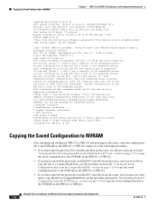
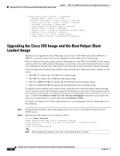
... flash memory on the NPE-G1 and NPE-G2 and contains a subset of bootflash:complete Continue? [confirm] Note Reformatting flash memory erases the current flash memory contents. 7-62 Network Processing Engine and Network Services Engine Installation and Configuration OL-4448-12 The boot helper (boot loader) image resides in "bootflash:". Follow the Software Center link under Service and Support. Continue? [confirm] Format operation will destroy all data in flash memory on your router. You need to the Cisco...
... flash memory on the NPE-G1 and NPE-G2 and contains a subset of bootflash:complete Continue? [confirm] Note Reformatting flash memory erases the current flash memory contents. 7-62 Network Processing Engine and Network Services Engine Installation and Configuration OL-4448-12 The boot helper (boot loader) image resides in "bootflash:". Follow the Software Center link under Service and Support. Continue? [confirm] Format operation will destroy all data in flash memory on your router. You need to the Cisco...
Installation Guide
Page 66
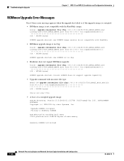
...; Upgrade command with incorrect file type: NPEG1-10# upgrade rom-monitor file tftp://00.0.00.0/biff/C7200_NPEG2_BOOT_ROM.bin from 00.0.00.0 (via GigabitEthernet0/1 OK - 524288 bytes] %Error:not srec file • A boot of main memory Readonly ROMMON initialized 7-66 Network Processing Engine and Network Services Engine Installation and Configuration OL-4448-12 Troubleshooting the Upgrade Chapter 7 NPE-G1 and NPE-G2 Installation and Configuration Information ROMmon Upgrade Error Messages One if these error message appears when the upgrade has failed...
...; Upgrade command with incorrect file type: NPEG1-10# upgrade rom-monitor file tftp://00.0.00.0/biff/C7200_NPEG2_BOOT_ROM.bin from 00.0.00.0 (via GigabitEthernet0/1 OK - 524288 bytes] %Error:not srec file • A boot of main memory Readonly ROMMON initialized 7-66 Network Processing Engine and Network Services Engine Installation and Configuration OL-4448-12 Troubleshooting the Upgrade Chapter 7 NPE-G1 and NPE-G2 Installation and Configuration Information ROMmon Upgrade Error Messages One if these error message appears when the upgrade has failed...


