
User Guide
Page 40
..., the clock and battery are dynamic Electro-Mechanical devices. Note If the lithium battery in ambient temperatures above 40oC. The Cisco 2801 router has two fans. The Cisco 2801 internal fans operate at three different speeds, running at the slower speeds to Cisco for various electronic reasons, and will eventually fail due to verify the validity of...
..., the clock and battery are dynamic Electro-Mechanical devices. Note If the lithium battery in ambient temperatures above 40oC. The Cisco 2801 router has two fans. The Cisco 2801 internal fans operate at three different speeds, running at the slower speeds to Cisco for various electronic reasons, and will eventually fail due to verify the validity of...

User Guide
Page 61
... will help you avoid environmentally caused equipment failures: • Ensure that the chassis cover and module rear panels are not available for Cisco 2801 routers. Damage from intake air, which also helps to flow within it is not congested, because each router generates heat. All empty..., ambient air temperature may interrupt and reduce the flow of vertical space between routers. • Enclosed racks must have louvered sides and a fan to equipment. The chassis is installed on slides, check the position of the equipment above. • When mounting a chassis in the "...
... will help you avoid environmentally caused equipment failures: • Ensure that the chassis cover and module rear panels are not available for Cisco 2801 routers. Damage from intake air, which also helps to flow within it is not congested, because each router generates heat. All empty..., ambient air temperature may interrupt and reduce the flow of vertical space between routers. • Enclosed racks must have louvered sides and a fan to equipment. The chassis is installed on slides, check the position of the equipment above. • When mounting a chassis in the "...

User Guide
Page 81
...OL T S 0 L PVDM1 PVDM0 AIM1 AIM0 95778 Attaching Optional Cable Management Bracket The optional cable management bracket provides attachment points for the Cisco 2801 and Cisco 2811 routers, attach the cable management bracket to the top with the heaviest component at the bottom of the rack if it is provided...the left or right rack-mount bracket using the screw provided, as power supplies, fans, or cards); OL-5786-03 Chassis Installation Procedures for 2-rack-unit-high Cisco 2821 and Cisco 2851 routers, you must take special precautions to ensure your safety: • This...
...OL T S 0 L PVDM1 PVDM0 AIM1 AIM0 95778 Attaching Optional Cable Management Bracket The optional cable management bracket provides attachment points for the Cisco 2801 and Cisco 2811 routers, attach the cable management bracket to the top with the heaviest component at the bottom of the rack if it is provided...the left or right rack-mount bracket using the screw provided, as power supplies, fans, or cards); OL-5786-03 Chassis Installation Procedures for 2-rack-unit-high Cisco 2821 and Cisco 2851 routers, you must take special precautions to ensure your safety: • This...

User Guide
Page 82
...Procedures for air circulation and antiskid protection. They provide space for Cisco 2800 Series Routers 10 OL-5786-03 Setting Up the Chassis Figure 13 Attaching the Optional Cable Management Bracket to the Cisco 2801 Router 95772 Cable management screw Figure 14 Attaching the Optional Cable ... side of the chassis. Setting the Chassis on a Desktop You can place Cisco 2800 series routers on the bottom of the chassis. For the chassis ground connection procedures, see the "Installing the Chassis Ground Connection" section on modules (such as power supplies, fans, or cards);
...Procedures for air circulation and antiskid protection. They provide space for Cisco 2800 Series Routers 10 OL-5786-03 Setting Up the Chassis Figure 13 Attaching the Optional Cable Management Bracket to the Cisco 2801 Router 95772 Cable management screw Figure 14 Attaching the Optional Cable ... side of the chassis. Setting the Chassis on a Desktop You can place Cisco 2800 series routers on the bottom of the chassis. For the chassis ground connection procedures, see the "Installing the Chassis Ground Connection" section on modules (such as power supplies, fans, or cards);
User Guide
Page 120
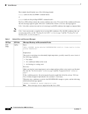
...the room temperature is not blocked. See also the "Site Environment" section on page 4 and the "Equipment Racks" section on the Cisco 2801. Call your router, see the "Reading System LEDs" section on page 4 and the "Reading Port and Module LEDs" section on ...detected OVERTEMPERATURE condition. System Messages The terminal should display one or more of the following conditions: • Fan failure • Air conditioner failure in your Cisco technical support representative for assistance, if necessary. If this condition persists, the environmental monitor might accompany them. ...
...the room temperature is not blocked. See also the "Site Environment" section on page 4 and the "Equipment Racks" section on the Cisco 2801. Call your router, see the "Reading System LEDs" section on page 4 and the "Reading Port and Module LEDs" section on ...detected OVERTEMPERATURE condition. System Messages The terminal should display one or more of the following conditions: • Fan failure • Air conditioner failure in your Cisco technical support representative for assistance, if necessary. If this condition persists, the environmental monitor might accompany them. ...

User Guide
Page 121
... rotating at the desired speed. Message, Meaning, and Recommended Action Error: %ENVMON-3-FAN_FAILED: Fan fan-number not rotating. Note The Cisco 2801 does not support RPS. Note The Cisco 2801 does not support RPS. Explanation: The specified fan (1, 2, or 3) is not applicable to the Cisco 2801. Amber Green - - Recommended action: Message is properly attached to the router. System Messages...
... rotating at the desired speed. Message, Meaning, and Recommended Action Error: %ENVMON-3-FAN_FAILED: Fan fan-number not rotating. Note The Cisco 2801 does not support RPS. Note The Cisco 2801 does not support RPS. Explanation: The specified fan (1, 2, or 3) is not applicable to the Cisco 2801. Amber Green - - Recommended action: Message is properly attached to the router. System Messages...

User Guide
Page 149
... the locations of the DIMMs, AIMs, PVDMs, and power supply in Cisco 2811 routers. Figure 8 Module Locations in Cisco 2801 Routers 13 12 14 15 11 8 9 10 16 17 95907 7 6 5 5 2 32 4 1 1 1 ILP fan vents/vent blocking plate 2 System fans 3 VIC or VWIC connector 4 VIC, VWIC, WIC, or HWIC connector... supply connector OL-5792-04 Installing and Upgrading Internal Modules in Cisco 2801 routers. Figure 10 and Figure 11 show the locations of the DIMMs, AIMs, PVDMs, and power supply in Cisco 2821 and Cisco 2851 routers. Locating Modules Locating Modules Figure 8 shows the locations...
... the locations of the DIMMs, AIMs, PVDMs, and power supply in Cisco 2811 routers. Figure 8 Module Locations in Cisco 2801 Routers 13 12 14 15 11 8 9 10 16 17 95907 7 6 5 5 2 32 4 1 1 1 ILP fan vents/vent blocking plate 2 System fans 3 VIC or VWIC connector 4 VIC, VWIC, WIC, or HWIC connector... supply connector OL-5792-04 Installing and Upgrading Internal Modules in Cisco 2801 routers. Figure 10 and Figure 11 show the locations of the DIMMs, AIMs, PVDMs, and power supply in Cisco 2821 and Cisco 2851 routers. Locating Modules Locating Modules Figure 8 shows the locations...

User Guide
Page 152
...-XXX 103978 1 AIM connectors 2 DRAM DIMMs 3 PVDMs 4 Power supply connectors 5 Fans Installing and Removing DRAM DIMMs Cisco 2801 routers have two DIMM connectors and are designed to the metal part of DRAM DIMM than the Cisco 2811, Cisco 2821, and Cisco 2851 routers. Note The Cisco 2801 uses a different type of the chassis. Installing and Removing DRAM DIMMs...
...-XXX 103978 1 AIM connectors 2 DRAM DIMMs 3 PVDMs 4 Power supply connectors 5 Fans Installing and Removing DRAM DIMMs Cisco 2801 routers have two DIMM connectors and are designed to the metal part of DRAM DIMM than the Cisco 2811, Cisco 2821, and Cisco 2851 routers. Note The Cisco 2801 uses a different type of the chassis. Installing and Removing DRAM DIMMs...

User Guide
Page 177
... screws that fasten the vent blocking plate to the chassis, and remove the vent blocking plate from the inline power (ILP) supply fan vents. Replacing the Power Supply Figure 35 Cisco 2801 Main Power Supply Removal . 4 3 5 103059 1 2 1 Main power supply fastening screws 2 Vent blocking plate fastening screws 3 Vent blocking plate 4 Main power connector...
... screws that fasten the vent blocking plate to the chassis, and remove the vent blocking plate from the inline power (ILP) supply fan vents. Replacing the Power Supply Figure 35 Cisco 2801 Main Power Supply Removal . 4 3 5 103059 1 2 1 Main power supply fastening screws 2 Vent blocking plate fastening screws 3 Vent blocking plate 4 Main power connector...

User Guide
Page 178
...fans should be visible through the vents that the vent blocking plate has been removed in Cisco 2800 Series Routers 38 OL-5792-04 Verify that were blocked by external AC power. The following sections describe how to install each type of IP phones attached to the router. Installing a Power Supply in a Cisco... An inline power (ILP) supply, driven by the vent blocking plate. Replacing the Power Supply Figure 36 Inserting the ILP Supply into the Cisco 2801 Router 4 3 2 103060 1 1 ILP supply fastening screws 2 ILP supply 3 ILP connector 4 Main power connector Step 6 Step 7 Step...
...fans should be visible through the vents that the vent blocking plate has been removed in Cisco 2800 Series Routers 38 OL-5792-04 Verify that were blocked by external AC power. The following sections describe how to install each type of IP phones attached to the router. Installing a Power Supply in a Cisco... An inline power (ILP) supply, driven by the vent blocking plate. Replacing the Power Supply Figure 36 Inserting the ILP Supply into the Cisco 2801 Router 4 3 2 103060 1 1 ILP supply fastening screws 2 ILP supply 3 ILP connector 4 Main power connector Step 6 Step 7 Step...
