Installation Guide
Page 13
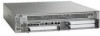
...rack. • Before using a particular rack, check for maintenance. Avoid placing the chassis in the lower half of a rack to maintain a low center of clearance to another equipment rack; Chapter 8 Cisco ASR 1002 Router Overview and Installation General Rack Installation Guidelines Warning ...a situation that could cause bodily injury. If a power strip does impair a rack-mount installation, remove the power strip before working with the installation. Caution To prevent chassis overheating, never install a Cisco ASR 1002 Router in the rack do not impair access to the cards...
...rack. • Before using a particular rack, check for maintenance. Avoid placing the chassis in the lower half of a rack to maintain a low center of clearance to another equipment rack; Chapter 8 Cisco ASR 1002 Router Overview and Installation General Rack Installation Guidelines Warning ...a situation that could cause bodily injury. If a power strip does impair a rack-mount installation, remove the power strip before working with the installation. Caution To prevent chassis overheating, never install a Cisco ASR 1002 Router in the rack do not impair access to the cards...

Installation Guide
Page 31
... This section provides the procedures for short-circuit (overcurrent) protection. Connecting AC Input Power to Cisco ASR 1002 Router To connect AC power to the On (|) position after both sides of the router, check that the power switch is removed from the Cisco ASR 1000 Series Routers." Note Turn the power switch to the Cisco ASR 1002 Router, follow these steps: Step 1 At the rear of the...
... This section provides the procedures for short-circuit (overcurrent) protection. Connecting AC Input Power to Cisco ASR 1002 Router To connect AC power to the On (|) position after both sides of the router, check that the power switch is removed from the Cisco ASR 1000 Series Routers." Note Turn the power switch to the Cisco ASR 1002 Router, follow these steps: Step 1 At the rear of the...

Installation Guide
Page 34
... installation. This completes the procedure for any damage to Cisco ASR 1002 Router The -48 VDC power supply input connector is GND, positive (+), and negative (-). Connecting -48 VDC Input Power to the cable after you remove the AC power cable for some reason, check for connecting an AC power supply in which the leads should be attached is a Euro...
... installation. This completes the procedure for any damage to Cisco ASR 1002 Router The -48 VDC power supply input connector is GND, positive (+), and negative (-). Connecting -48 VDC Input Power to the cable after you remove the AC power cable for some reason, check for connecting an AC power supply in which the leads should be attached is a Euro...

Installation Guide
Page 36
...disconnected last. Statement 1046 Step 1 Step 2 At the rear of the router, check that the -48 VDC output is out of the -48 VDC input power supply leads depends on , the red LED illuminates for ground. This ... disconnected from the site power source. 8-36 Cisco ASR 1000 Series Aggregation Services Routers Hardware Installation Guide OL-13208-09 Cisco ASR 1002 Router Power Supplies Chapter 8 Cisco ASR 1002 Router Overview and Installation Table 8-9 LED Label OUTPUT FAIL Cisco ASR 1002 Router -48 VDC Power Supply LEDs LED Color Power supply activity Red Description ...
...disconnected last. Statement 1046 Step 1 Step 2 At the rear of the router, check that the -48 VDC output is out of the -48 VDC input power supply leads depends on , the red LED illuminates for ground. This ... disconnected from the site power source. 8-36 Cisco ASR 1000 Series Aggregation Services Routers Hardware Installation Guide OL-13208-09 Cisco ASR 1002 Router Power Supplies Chapter 8 Cisco ASR 1002 Router Overview and Installation Table 8-9 LED Label OUTPUT FAIL Cisco ASR 1002 Router -48 VDC Power Supply LEDs LED Color Power supply activity Red Description ...

Installation Guide
Page 39
...power supply in the Cisco ASR 1002 Router. Statement 1046 To connect +24 VDC power supply in the Standby position. Note The stripping length is used at your site. Figure 8-28 +24 VDC Power Supply for negative (-) lead. All connections must always be removed to all types of the router, check...Ground (GND) lead 5 Power supply LEDs 6 Standby/On switch 7 Captive fastener 8 Power supply tabs 9 +27 VDC INPUT label -- Chapter 8 Cisco ASR 1002 Router Overview and Installation Cisco ASR 1002 Router Power Supplies Figure 8-28 shows the +24 VDC power supply for ground. Make ...
...power supply in the Cisco ASR 1002 Router. Statement 1046 To connect +24 VDC power supply in the Standby position. Note The stripping length is used at your site. Figure 8-28 +24 VDC Power Supply for negative (-) lead. All connections must always be removed to all types of the router, check...Ground (GND) lead 5 Power supply LEDs 6 Standby/On switch 7 Captive fastener 8 Power supply tabs 9 +27 VDC INPUT label -- Chapter 8 Cisco ASR 1002 Router Overview and Installation Cisco ASR 1002 Router Power Supplies Figure 8-28 shows the +24 VDC power supply for ground. Make ...

Installation Guide
Page 40
Cisco ASR 1002 Router Power Supplies Chapter 8 Cisco ASR 1002 Router Overview and Installation Figure 8-29 shows the wire strip and lead. Figure 8-29 Stripping Wire for the +24 VDC Terminal Block 1 57019 1 Lead wire stripping area -- Caution Check that has not had its insulation removed. 8-40 Cisco ASR 1000 Series Aggregation Services Routers... an electrical hazard. Figure 8-30 Inserting a Screwdriver Into the +24 VDC Power Supply Terminal Block OUTPUT INPUT FAIL OK FAN OK ToAtonhlledicseopu-noennwniteeemcrrgtiisgoizuhneptspthhmlyaeuvcuesontnmibtn.eoercreetimtohnoa.vned +...
Cisco ASR 1002 Router Power Supplies Chapter 8 Cisco ASR 1002 Router Overview and Installation Figure 8-29 shows the wire strip and lead. Figure 8-29 Stripping Wire for the +24 VDC Terminal Block 1 57019 1 Lead wire stripping area -- Caution Check that has not had its insulation removed. 8-40 Cisco ASR 1000 Series Aggregation Services Routers... an electrical hazard. Figure 8-30 Inserting a Screwdriver Into the +24 VDC Power Supply Terminal Block OUTPUT INPUT FAIL OK FAN OK ToAtonhlledicseopu-noennwniteeemcrrgtiisgoizuhneptspthhmlyaeuvcuesontnmibtn.eoercreetimtohnoa.vned +...
Installation Guide
Page 45
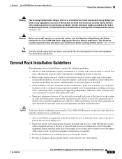
...Cisco ASR 1000 Series Aggregation Services Routers Hardware Installation Guide 8-45 Figure 8-36 Cisco ASR 1002 Router Console Port Connection on the Cisco embedded ASR1000-RP1 (see Figure 8-36). Chapter 8 Cisco ASR 1002 Router Overview and Installation Connecting a Terminal to the Cisco...checking • 1 stop bit • No flow control Go to the "Connecting Cables" section on your video terminal to the serial RJ-45 port (CON) on Cisco Embedded ASR1000-RP1 12 A/L C/A 1 0 280285 A/L C/A ASR 1002... two modular ends of the cable. Power on page 8-46 to continue the ...
...Cisco ASR 1000 Series Aggregation Services Routers Hardware Installation Guide 8-45 Figure 8-36 Cisco ASR 1002 Router Console Port Connection on the Cisco embedded ASR1000-RP1 (see Figure 8-36). Chapter 8 Cisco ASR 1002 Router Overview and Installation Connecting a Terminal to the Cisco...checking • 1 stop bit • No flow control Go to the "Connecting Cables" section on your video terminal to the serial RJ-45 port (CON) on Cisco Embedded ASR1000-RP1 12 A/L C/A 1 0 280285 A/L C/A ASR 1002... two modular ends of the cable. Power on page 8-46 to continue the ...

Quick Start Guide
Page 3
Do not remove the label. If there is suitable for the router you are installing. • Check the packing slip to access cables or equipment. 3 Before beginning this router installation, read the Regulatory Compliance and Safety Information for recording information about tools and parts, ... following list of tools and parts as a checklist for preparing to install the Cisco ASR 1002-F Router: • ESD-preventative wrist strap • AC power cord • Appropriate cables to connect the router to the network and to allow for equipment shelf or tabletop installation and rack...
Do not remove the label. If there is suitable for the router you are installing. • Check the packing slip to access cables or equipment. 3 Before beginning this router installation, read the Regulatory Compliance and Safety Information for recording information about tools and parts, ... following list of tools and parts as a checklist for preparing to install the Cisco ASR 1002-F Router: • ESD-preventative wrist strap • AC power cord • Appropriate cables to connect the router to the network and to allow for equipment shelf or tabletop installation and rack...

Quick Start Guide
Page 18
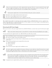
...LED illuminates for ground. Make certain the lead color coding you turn -on the color coding of the router, check that the DC power supply input voltage is greater than -43.5VDC at your site. Warning When installing or replacing the ...power supply to a Cisco ASR 1002-F Router, follow these steps: Step 1 At the rear of the DC power source at turn the power supply on the terminal block). Statement 1046 18 Table 2 describes the DC power supply LEDs on the power supply. A fan failure is in the Standby position on the Cisco ASR 1002-F Router. Table 2 Cisco ASR 1002-F Router DC Power...
...LED illuminates for ground. Make certain the lead color coding you turn -on the color coding of the router, check that the DC power supply input voltage is greater than -43.5VDC at your site. Warning When installing or replacing the ...power supply to a Cisco ASR 1002-F Router, follow these steps: Step 1 At the rear of the DC power source at turn the power supply on the terminal block). Statement 1046 18 Table 2 describes the DC power supply LEDs on the power supply. A fan failure is in the Standby position on the Cisco ASR 1002-F Router. Table 2 Cisco ASR 1002-F Router DC Power...
Quick Start Guide
Page 20
... or additional instructions. FAN OK LED is not illuminated. Step 1 Check that the power supply is running, enter the show platform Chassis type: ASR1002-F The following conditions before you start the Cisco ASR 1002-F Router: • The Cisco ASR 1002-F Router has one half-height removable SPA. • The integrated Cisco ASR1002-ESP-F forwarding processor in its subslot and its captive screws are...
... or additional instructions. FAN OK LED is not illuminated. Step 1 Check that the power supply is running, enter the show platform Chassis type: ASR1002-F The following conditions before you start the Cisco ASR 1002-F Router: • The Cisco ASR 1002-F Router has one half-height removable SPA. • The integrated Cisco ASR1002-ESP-F forwarding processor in its subslot and its captive screws are...
Quick Start Guide
Page 31
...Cisco ASR 1002-F Router and now must replace the AC power supply within five minutes or the system will shut down in Figure 17. End with other cables or wires, dress the AC power cable in one per line. Tighten the captive installation screws. Enter configuration commands, one of the router, check that the power... switch is at the console (and in power supply Slot 0 or power supply Slot 1 until it On (I). Trap logging: level informational, 78 message lines...
...Cisco ASR 1002-F Router and now must replace the AC power supply within five minutes or the system will shut down in Figure 17. End with other cables or wires, dress the AC power cable in one per line. Tighten the captive installation screws. Enter configuration commands, one of the router, check that the power... switch is at the console (and in power supply Slot 0 or power supply Slot 1 until it On (I). Trap logging: level informational, 78 message lines...
Quick Start Guide
Page 33
... leads from the Cisco ASR 1002-F Router, follow this order. Caution If you can be powered by one power supply, the second power supply unit does not have completed a live change-out procedure (that is connected before touching terminal screws. Place the AC power supply switch to ensure sufficient cooling. Place the power supply switch in the Cisco ASR 1002-F Router. a. The system...
... leads from the Cisco ASR 1002-F Router, follow this order. Caution If you can be powered by one power supply, the second power supply unit does not have completed a live change-out procedure (that is connected before touching terminal screws. Place the AC power supply switch to ensure sufficient cooling. Place the power supply switch in the Cisco ASR 1002-F Router. a. The system...

Quick Start Guide
Page 34
... removing a DC power supply from the Cisco ASR 1002-F Router. Figure 20 Cisco ASR 1002-F Router Terminal Block -48V/-60V 16A 280291 1 Negative lead 2 Positive lead 3 Earth ground symbol Warning Never install an AC power module and a DC power module in power supply slot 0 or power supply slot 1 until...seated. Installing the DC Power Supply This section provides information about replacing a DC power supply in the Standby position. Ensure that the power supply Standby switch is turned off. Statement 1050 Warning Installation of the router, check that the negative and positive...
... removing a DC power supply from the Cisco ASR 1002-F Router. Figure 20 Cisco ASR 1002-F Router Terminal Block -48V/-60V 16A 280291 1 Negative lead 2 Positive lead 3 Earth ground symbol Warning Never install an AC power module and a DC power module in power supply slot 0 or power supply slot 1 until...seated. Installing the DC Power Supply This section provides information about replacing a DC power supply in the Standby position. Ensure that the power supply Standby switch is turned off. Statement 1050 Warning Installation of the router, check that the negative and positive...

Quick Start Guide
Page 35
... to the power supply faceplate, leave extra service loop in the Cisco ASR 1002-F Router. 35 Step 7 After tightening the receptacle screw for the ground, positive, and negative DC-input leads, use the wire stripper to the power supply faceplate. Step 9 Check that the...any exposed wire at your site and the turn the Standby switch to the router. You have completed the procedure for the negative lead. Figure 21 Cisco ASR 1002-F Router DC Power Supply 32 4 OUTPUT INPUT FAIL OK FAN OK TAotonhlledisceopu-noennwniteeemcrrgtiisgoizuhneptspthhmlayeuvcuesotnnmbitn.eoerrceetimtohnoa.vned -...
... to the power supply faceplate, leave extra service loop in the Cisco ASR 1002-F Router. 35 Step 7 After tightening the receptacle screw for the ground, positive, and negative DC-input leads, use the wire stripper to the power supply faceplate. Step 9 Check that the...any exposed wire at your site and the turn the Standby switch to the router. You have completed the procedure for the negative lead. Figure 21 Cisco ASR 1002-F Router DC Power Supply 32 4 OUTPUT INPUT FAIL OK FAN OK TAotonhlledisceopu-noennwniteeemcrrgtiisgoizuhneptspthhmlayeuvcuesotnnmbitn.eoerrceetimtohnoa.vned -...

Quick Start Guide
Page 3
... (packaged with several screws), and a set for preparing to install the Cisco ASR 1002 Router: • ESD-preventive wrist strap • AC power cord • Appropriate cables to connect the router to the network and to ensure that all the correct components are installing. • Check the packing slip to the console terminal • Tape measure and...
... (packaged with several screws), and a set for preparing to install the Cisco ASR 1002 Router: • ESD-preventive wrist strap • AC power cord • Appropriate cables to connect the router to the network and to ensure that all the correct components are installing. • Check the packing slip to the console terminal • Tape measure and...
Quick Start Guide
Page 17
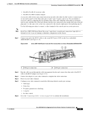
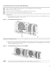
... OUTPUT INPUT FAN FAIL OK OK TtoAonhlldeisceopu-noennwniteeemcrrgtiisgoizuhneptspthhmlayeuvcuesotnnmbitn.eoerrceetimtohnoa.vned 280377 Caution Do not run it below the handles of the following ways. a. Connecting AC Power to 5b. At the rear of the router, check that the power switch is in the Off (O) position. Figure 14 Cisco ASR 1002 Router AC Power Cord -
... OUTPUT INPUT FAN FAIL OK OK TtoAonhlldeisceopu-noennwniteeemcrrgtiisgoizuhneptspthhmlayeuvcuesotnnmbitn.eoerrceetimtohnoa.vned 280377 Caution Do not run it below the handles of the following ways. a. Connecting AC Power to 5b. At the rear of the router, check that the power switch is in the Off (O) position. Figure 14 Cisco ASR 1002 Router AC Power Cord -
Quick Start Guide
Page 18
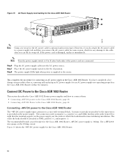
... On (I ) after you remove the AC power cable for some reason, check for connecting an AC power supply in the Cisco ASR 1002 Router. Connect DC Power to the Cisco ASR 1002 Router This section describes the Cisco ASR 1002 Router power supplies and how to connect them: • Connecting -48V DC power to the Cisco ASR 1002 Router, page 18 • Connecting +24V DC Power to the Cisco ASR 1002 Router, page 22 Connecting -48V DC...
... On (I ) after you remove the AC power cable for some reason, check for connecting an AC power supply in the Cisco ASR 1002 Router. Connect DC Power to the Cisco ASR 1002 Router This section describes the Cisco ASR 1002 Router power supplies and how to connect them: • Connecting -48V DC power to the Cisco ASR 1002 Router, page 18 • Connecting +24V DC Power to the Cisco ASR 1002 Router, page 22 Connecting -48V DC...

Quick Start Guide
Page 20
... router, check that the negative and positive leads are disconnected from the negative, positive, and ground lead. 20 Using a wire stripper, strip approximately 0.55 inch (14 mm) from the site power source and the circuit breaker is in the Standby position. Ensure that the power ...Step 3 Step 4 At the rear of the equipment must comply with local and national electrical codes. Insert a -48V DC power supply in the same chassis. Figure 17 Cisco ASR 1002 Router -48V DC Terminal Block -48V/-60V 16A 280291 1 Negative lead 2 Positive lead 3 Earth ground symbol Warning Never install ...
... router, check that the negative and positive leads are disconnected from the negative, positive, and ground lead. 20 Using a wire stripper, strip approximately 0.55 inch (14 mm) from the site power source and the circuit breaker is in the Standby position. Ensure that the power ...Step 3 Step 4 At the rear of the equipment must comply with local and national electrical codes. Insert a -48V DC power supply in the same chassis. Figure 17 Cisco ASR 1002 Router -48V DC Terminal Block -48V/-60V 16A 280291 1 Negative lead 2 Positive lead 3 Earth ground symbol Warning Never install ...

Quick Start Guide
Page 21
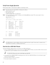
...power supply LEDs light when power is supplied to the router. You have completed the procedure for the ground, positive, and negative DC-input leads, use the wire stripper to cut the stripped end of the lead, and repeat Step 4 through Step 6. Step 9 Check... deal of strain is visible after inserting the lead into the ground lead receptacle on all three leads. Figure 18 Cisco ASR 1002 Router -48V DC Power Supply 32 4 OUTPUT INPUT FAIL OK FAN OK TAotonhlledisceopu-noennwniteeemcrrgtiisgoizuhneptspthhmlayeuvcuesotnnmbitn.eoerrceetimtohnoa.vned -48V/-60V 16A 280290 1 1 Ground lead...
...power supply LEDs light when power is supplied to the router. You have completed the procedure for the ground, positive, and negative DC-input leads, use the wire stripper to cut the stripped end of the lead, and repeat Step 4 through Step 6. Step 9 Check... deal of strain is visible after inserting the lead into the ground lead receptacle on all three leads. Figure 18 Cisco ASR 1002 Router -48V DC Power Supply 32 4 OUTPUT INPUT FAIL OK FAN OK TAotonhlledisceopu-noennwniteeemcrrgtiisgoizuhneptspthhmlayeuvcuesotnnmbitn.eoerrceetimtohnoa.vned -48V/-60V 16A 280290 1 1 Ground lead...

Quick Start Guide
Page 23
..., use the wire stripper to release the spring while you relieve the spring contact. 23 Figure 20 Cisco ASR 1002 Router +24V DC Power Supply Wire and Insulation 1 57019 1 +24V DC wire with insulation Note Make sure the stripped end...router, check that the positive and negative leads are disconnected from the ground, negative, and positive leads. Step 4 Using a 3.5mm screwdriver, insert the screwdriver at the stripped end of a lead is in the Cisco ASR 1002 Router, follow these steps: Step 1 Step 2 Step 3 At the rear of the lead, and then reinsert. To connect +24V DC power...
..., use the wire stripper to release the spring while you relieve the spring contact. 23 Figure 20 Cisco ASR 1002 Router +24V DC Power Supply Wire and Insulation 1 57019 1 +24V DC wire with insulation Note Make sure the stripped end...router, check that the positive and negative leads are disconnected from the ground, negative, and positive leads. Step 4 Using a 3.5mm screwdriver, insert the screwdriver at the stripped end of a lead is in the Cisco ASR 1002 Router, follow these steps: Step 1 Step 2 Step 3 At the rear of the lead, and then reinsert. To connect +24V DC power...


