Installation Guide
Page 1
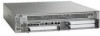
... Shared Port Adapter Cables, page 8-28 • Connecting the Console and Auxiliary Port Cables, page 8-29 • Cisco ASR 1002 Router Power Supplies, page 8-30 • Connecting a Terminal to the Cisco ASR1000-RP1 Console Port, page 8-44 • Connecting Cables, page 8-46 • Auxiliary Connection, page 8-46 Cisco ASR 1002 Router Description The Cisco ASR 1002 Router is part of the Cisco aggregation services family of...
... Shared Port Adapter Cables, page 8-28 • Connecting the Console and Auxiliary Port Cables, page 8-29 • Cisco ASR 1002 Router Power Supplies, page 8-30 • Connecting a Terminal to the Cisco ASR1000-RP1 Console Port, page 8-44 • Connecting Cables, page 8-46 • Auxiliary Connection, page 8-46 Cisco ASR 1002 Router Description The Cisco ASR 1002 Router is part of the Cisco aggregation services family of...

Installation Guide
Page 2
... the chassis and not field upgradeable. Cisco ASR 1002 Router Description Chapter 8 Cisco ASR 1002 Router Overview and Installation The Cisco ASR 1002 Router supports: • Cisco ASR1000-ESP5 or Cisco ASR1000-ESP10 as a field-replaceable unit (FRU) • The Cisco Embedded Route Processor which supports 2MB upgradeable BootROM and 8 GB eUSB bulk storage. • 1 + 1 redundant AC or DC power supplies. • Stratum-3 network clocking per GR...
... the chassis and not field upgradeable. Cisco ASR 1002 Router Description Chapter 8 Cisco ASR 1002 Router Overview and Installation The Cisco ASR 1002 Router supports: • Cisco ASR1000-ESP5 or Cisco ASR1000-ESP10 as a field-replaceable unit (FRU) • The Cisco Embedded Route Processor which supports 2MB upgradeable BootROM and 8 GB eUSB bulk storage. • 1 + 1 redundant AC or DC power supplies. • Stratum-3 network clocking per GR...

Installation Guide
Page 3
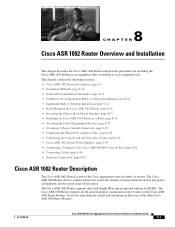
... 8 1 Chassis ESD socket 2 AC power supply slot number 0 3 AC power supply On (|) /Off (O) switch 4 AC power supply LEDs 7 5 AC power supply fan 6 AC power supply captive installation screw 7 AC power supply slot number 1 8 AC power inlet Figure 8-3 shows the Cisco ASR 1002 Router DC power supply. Figure 8-2 Cisco ASR 1002 Router AC Power Supply 12 34 5 6 0 OUTPUT INPUT FAN FAIL OK OK This unit might have more than one power supply connection. Figure 8-3 Cisco ASR 1002 Router DC Power Supply 12 34 5 6 0 OUTPUT...
... 8 1 Chassis ESD socket 2 AC power supply slot number 0 3 AC power supply On (|) /Off (O) switch 4 AC power supply LEDs 7 5 AC power supply fan 6 AC power supply captive installation screw 7 AC power supply slot number 1 8 AC power inlet Figure 8-3 shows the Cisco ASR 1002 Router DC power supply. Figure 8-2 Cisco ASR 1002 Router AC Power Supply 12 34 5 6 0 OUTPUT INPUT FAN FAIL OK OK This unit might have more than one power supply connection. Figure 8-3 Cisco ASR 1002 Router DC Power Supply 12 34 5 6 0 OUTPUT...
Installation Guide
Page 4
... rear of the chassis. Cisco ASR 1002 Router Slot Numbering The Cisco ASR 1002 Router contains one Cisco embedded ASR1002-RP1 which is located on the Cisco embedded ASR1000-RP1 board. The Cisco ASR 1002 Router consists of any Cisco ASR 1000 Series Routers are field-replaceable units Cisco ASR 1000 Series Aggregation Services Routers Hardware Installation Guide 8-4 OL-13208-09 Caution Use only AC power supplies or DC power supplies in the SPA 0 location...
... rear of the chassis. Cisco ASR 1002 Router Slot Numbering The Cisco ASR 1002 Router contains one Cisco embedded ASR1002-RP1 which is located on the Cisco embedded ASR1000-RP1 board. The Cisco ASR 1002 Router consists of any Cisco ASR 1000 Series Routers are field-replaceable units Cisco ASR 1000 Series Aggregation Services Routers Hardware Installation Guide 8-4 OL-13208-09 Caution Use only AC power supplies or DC power supplies in the SPA 0 location...
Installation Guide
Page 6
... the Cisco ASR 1002 Router The Cisco ASR 1002 Router power supply module supports the following Cisco power supplies: • AC power supply operates between 85VAC to 264VAC and DC operates between -40.5 to -72VDC • -48 VDC power supply operates between • +24 VDC power supply operates Cisco ASR 1000 Series Aggregation Services Routers Hardware Installation Guide 8-6 OL-13208-09 Code has successfully downloaded and is in the Cisco ASR 1002 Router. Power Supplies in the Power-Up...
... the Cisco ASR 1002 Router The Cisco ASR 1002 Router power supply module supports the following Cisco power supplies: • AC power supply operates between 85VAC to 264VAC and DC operates between -40.5 to -72VDC • -48 VDC power supply operates between • +24 VDC power supply operates Cisco ASR 1000 Series Aggregation Services Routers Hardware Installation Guide 8-6 OL-13208-09 Code has successfully downloaded and is in the Cisco ASR 1002 Router. Power Supplies in the Power-Up...

Installation Guide
Page 7
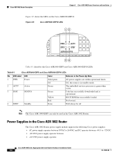
... more than one power supply connection. AC Power Supply for Cisco ASR 1002 Router The AC power supply input inlet is off . LED is turned off to de-energize the unit. 280288 1 8 7 OL-13208-09 Cisco ASR 1000 Series Aggregation Services Routers Hardware Installation Guide 8-7 Figure 8-6 AC Power Supply for the Cisco ASR 1002 Router. The Cisco ASR 1002 Router supports up to 470 W output (AC and DC Input). Table 8-2 Cisco ASR 1002 Router AC Power Supply LEDs LED...
... more than one power supply connection. AC Power Supply for Cisco ASR 1002 Router The AC power supply input inlet is off . LED is turned off to de-energize the unit. 280288 1 8 7 OL-13208-09 Cisco ASR 1000 Series Aggregation Services Routers Hardware Installation Guide 8-7 Figure 8-6 AC Power Supply for the Cisco ASR 1002 Router. The Cisco ASR 1002 Router supports up to 470 W output (AC and DC Input). Table 8-2 Cisco ASR 1002 Router AC Power Supply LEDs LED...

Installation Guide
Page 8
... polarity, one negative polarity, and one ground wire. Cisco ASR 1002 Router Description Chapter 8 Cisco ASR 1002 Router Overview and Installation 1 Chassis ESD socket 2 AC power supply slot number 0 3 AC power supply On (|) /Off (O) switch 4 AC power supply LEDs 5 AC power supply fan 6 AC power supply captive installation screw 7 AC power supply slot number 1 8 AC power supply inlet -48 VDC Power Supply for Cisco ASR 1002 Router The -48 VDC power supply input connector is compliant with two captive screws...
... polarity, one negative polarity, and one ground wire. Cisco ASR 1002 Router Description Chapter 8 Cisco ASR 1002 Router Overview and Installation 1 Chassis ESD socket 2 AC power supply slot number 0 3 AC power supply On (|) /Off (O) switch 4 AC power supply LEDs 5 AC power supply fan 6 AC power supply captive installation screw 7 AC power supply slot number 1 8 AC power supply inlet -48 VDC Power Supply for Cisco ASR 1002 Router The -48 VDC power supply input connector is compliant with two captive screws...

Installation Guide
Page 9
... end of the minimum or above the high end of the Cisco ASR 1002 Router. The LED illuminates s green when all fans are described in Table 8-3. OL-13208-09 Cisco ASR 1000 Series Aggregation Services Routers Hardware Installation Guide 8-9 Chapter 8 Cisco ASR 1002 Router Overview and Installation Cisco ASR 1002 Router Description Table 8-3 The Cisco ASR 1002 Router -48 VDC power supply LEDs are operational. Led illuminates red to around 20...
... end of the minimum or above the high end of the Cisco ASR 1002 Router. The LED illuminates s green when all fans are described in Table 8-3. OL-13208-09 Cisco ASR 1000 Series Aggregation Services Routers Hardware Installation Guide 8-9 Chapter 8 Cisco ASR 1002 Router Overview and Installation Cisco ASR 1002 Router Description Table 8-3 The Cisco ASR 1002 Router -48 VDC power supply LEDs are operational. Led illuminates red to around 20...

Installation Guide
Page 10
... power supply connection. Figure 8-8 shows the +24 VDC Power Supply for the Cisco ASR 1002 Router. The +24 VDC power supply uses a spring-loaded terminal block. Use the tie wraps to support input current. Cisco ASR 1002 Router Description Chapter 8 Cisco ASR 1002 Router Overview and Installation The Cisco ASR 1002 Router has two of the chassis rear. there are zero (0) on the right side of the same type power supplies in power supply slot 0 and power supply...
... power supply connection. Figure 8-8 shows the +24 VDC Power Supply for the Cisco ASR 1002 Router. The +24 VDC power supply uses a spring-loaded terminal block. Use the tie wraps to support input current. Cisco ASR 1002 Router Description Chapter 8 Cisco ASR 1002 Router Overview and Installation The Cisco ASR 1002 Router has two of the chassis rear. there are zero (0) on the right side of the same type power supplies in power supply slot 0 and power supply...

Installation Guide
Page 11
...power supply on the terminal block). OL-13208-09 Cisco ASR 1000 Series Aggregation Services Routers Hardware Installation Guide 8-11 Chapter 8 Cisco ASR 1002 Router Overview and Installation Cisco ASR 1002 Router Description Table 8-5 The Cisco ASR 1002 Router +24 VDC power supply LEDs are used for redundant operation. Note Two power supplies...is still a voltage present (voltage on , the red LED illuminates for Cisco ASR 1002 Router The +24 VDC power supply output tolerance is reached, the power supply does not resume operation until the input voltage has reached 20.0 volts +/- ...
...power supply on the terminal block). OL-13208-09 Cisco ASR 1000 Series Aggregation Services Routers Hardware Installation Guide 8-11 Chapter 8 Cisco ASR 1002 Router Overview and Installation Cisco ASR 1002 Router Description Table 8-5 The Cisco ASR 1002 Router +24 VDC power supply LEDs are used for redundant operation. Note Two power supplies...is still a voltage present (voltage on , the red LED illuminates for Cisco ASR 1002 Router The +24 VDC power supply output tolerance is reached, the power supply does not resume operation until the input voltage has reached 20.0 volts +/- ...
Installation Guide
Page 12
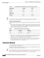
... end of the minimum or above the high end of the maximum limits (as the power supplies. 8-12 Cisco ASR 1000 Series Aggregation Services Routers Hardware Installation Guide OL-13208-09 Installation Methods Chapter 8 Cisco ASR 1002 Router Overview and Installation Table 8-6 Cisco ASR 1002 Router +24 VDC Power System Output Voltage and Current Output Voltage Minimum Nominal Maximum Output Current Minimum Maximum +12...
... end of the minimum or above the high end of the maximum limits (as the power supplies. 8-12 Cisco ASR 1000 Series Aggregation Services Routers Hardware Installation Guide OL-13208-09 Installation Methods Chapter 8 Cisco ASR 1002 Router Overview and Installation Table 8-6 Cisco ASR 1002 Router +24 VDC Power System Output Voltage and Current Output Voltage Minimum Nominal Maximum Output Current Minimum Maximum +12...
Installation Guide
Page 14
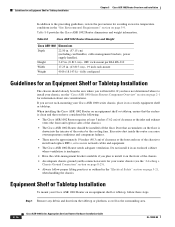
...card handles, cable-management brackets, power supply handles). If you have not determined where to install it in the "Site Environmental Requirements" section on page 2-1 for information about site considerations. When installing the Cisco ASR 1002 Router on an equipment shelf or ...8226; Have the cable-management bracket available if you plan to install your router chassis (see the "Cisco ASR 1000 Series Routers Component Overview" section on page 5-9. Table 8-8 Cisco ASR 1002 Router Dimensions and Weight Cisco ASR 1002 Dimensions Depth 22.50 in . (43.815 cm) - 19 inch...
...card handles, cable-management brackets, power supply handles). If you have not determined where to install it in the "Site Environmental Requirements" section on page 2-1 for information about site considerations. When installing the Cisco ASR 1002 Router on an equipment shelf or ...8226; Have the cable-management bracket available if you plan to install your router chassis (see the "Cisco ASR 1000 Series Routers Component Overview" section on page 5-9. Table 8-8 Cisco ASR 1002 Router Dimensions and Weight Cisco ASR 1002 Dimensions Depth 22.50 in . (43.815 cm) - 19 inch...
Installation Guide
Page 22
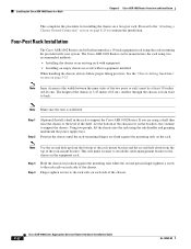
...lifting practices. Let the bottom of the chassis. 8-22 Cisco ASR 1000 Series Aggregation Services Routers Hardware Installation Guide OL-13208-09 Installing the Cisco ASR 1002 Router in a Rack Chapter 8 Cisco ASR 1002 Router Overview and Installation This completes the procedure for installing the ...power supply bays. See the "Chassis-Lifting Guidelines" section on page 8-25 to the "Attaching a Chassis Ground Connection" section on page 5-23. Airflow through the chassis is from the top of the chassis is stabilized. Finger-tighten screws to support the Cisco ASR 1002 Router...
...lifting practices. Let the bottom of the chassis. 8-22 Cisco ASR 1000 Series Aggregation Services Routers Hardware Installation Guide OL-13208-09 Installing the Cisco ASR 1002 Router in a Rack Chapter 8 Cisco ASR 1002 Router Overview and Installation This completes the procedure for installing the ...power supply bays. See the "Chassis-Lifting Guidelines" section on page 8-25 to the "Attaching a Chassis Ground Connection" section on page 5-23. Airflow through the chassis is from the top of the chassis is stabilized. Finger-tighten screws to support the Cisco ASR 1002 Router...

Installation Guide
Page 27
OL-13208-09 Cisco ASR 1000 Series Aggregation Services Routers Hardware Installation Guide 8-27 Locate the chassis ground connector on the left to avoid having the grounding wire overlapping the power supply. Chapter 8 Cisco ASR 1002 Router Overview and Installation Attaching a Chassis Ground Connection Figure 8-18 shows the parts of your chassis. Figure 8-18 Parts of the Grounding Lug 3 4 2 50536 1 Chassis ground connector holes 2 Grounding lug 1 3 Ground lug screws 4 Ground wire Step 3 Step 4 Attach the grounding lug with the wire on the side of the grounding lug.
OL-13208-09 Cisco ASR 1000 Series Aggregation Services Routers Hardware Installation Guide 8-27 Locate the chassis ground connector on the left to avoid having the grounding wire overlapping the power supply. Chapter 8 Cisco ASR 1002 Router Overview and Installation Attaching a Chassis Ground Connection Figure 8-18 shows the parts of your chassis. Figure 8-18 Parts of the Grounding Lug 3 4 2 50536 1 Chassis ground connector holes 2 Grounding lug 1 3 Ground lug screws 4 Ground wire Step 3 Step 4 Attach the grounding lug with the wire on the side of the grounding lug.
Installation Guide
Page 30
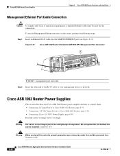
... part of the safety design of the RJ-45 cable to Cisco ASR 1002 Router, page 8-34 • Connecting Cisco +24 VDC Power Supply, page 8-38 Read the safety warnings before you install the unit, the ground connection must be made first and disconnected last. Cisco ASR 1002 Router Power Supplies Chapter 8 Cisco ASR 1002 Router Overview and Installation Management Ethernet Port Cable Connection Caution To comply...
... part of the safety design of the RJ-45 cable to Cisco ASR 1002 Router, page 8-34 • Connecting Cisco +24 VDC Power Supply, page 8-38 Read the safety warnings before you install the unit, the ground connection must be made first and disconnected last. Cisco ASR 1002 Router Power Supplies Chapter 8 Cisco ASR 1002 Router Overview and Installation Management Ethernet Port Cable Connection Caution To comply...

Installation Guide
Page 31
... rated not greater than: AC power supplies 20 A and DC power supplies 30 A. OL-13208-09 Cisco ASR 1000 Series Aggregation Services Routers Hardware Installation Guide 8-31 Statement 1024 Warning This unit has two power supply connections. All connections must be made first and disconnected last. Connecting AC Input Power to Cisco ASR 1002 Router To connect AC power to the Cisco ASR 1002 Router, follow these steps: Step...
... rated not greater than: AC power supplies 20 A and DC power supplies 30 A. OL-13208-09 Cisco ASR 1000 Series Aggregation Services Routers Hardware Installation Guide 8-31 Statement 1024 Warning This unit has two power supply connections. All connections must be made first and disconnected last. Connecting AC Input Power to Cisco ASR 1002 Router To connect AC power to the Cisco ASR 1002 Router, follow these steps: Step...

Installation Guide
Page 32
... power supply handle as shown in one power supply connection. Figure 8-22 Cisco ASR 1002 Router AC Power Supply Labels 12 0 34 OUTPUT INPUT FAN FAIL OK OK This unit might have more than one power supply connection. Alternatively, proceed to de-energize the unit. 5 6 8 OUTPUT INPUT FAN FAIL OK OK This unit might have more than one of the Cisco ASR 1002 Router AC power supply. Cisco ASR 1002 Router Power Supplies Chapter 8 Cisco ASR 1002 Router...
... power supply handle as shown in one power supply connection. Figure 8-22 Cisco ASR 1002 Router AC Power Supply Labels 12 0 34 OUTPUT INPUT FAN FAIL OK OK This unit might have more than one power supply connection. Alternatively, proceed to de-energize the unit. 5 6 8 OUTPUT INPUT FAN FAIL OK OK This unit might have more than one of the Cisco ASR 1002 Router AC power supply. Cisco ASR 1002 Router Power Supplies Chapter 8 Cisco ASR 1002 Router...
Installation Guide
Page 33
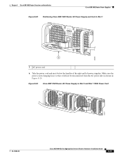
Figure 8-24 Cisco ASR 1002 Router AC Power Supply in Slot 1 OUTPUT INPUT FAN FAIL OK OK TAtoonhlldeisceopu-noennwniteeemcrrgtiisgoizuhneptspthhmlyaeuvcuesontnmibtn.eoercreetimtohnoa.vned 280383 1 1 AC power cord b. Chapter 8 Cisco ASR 1002 Router Overview and Installation Cisco ASR 1002 Router Power Supplies Figure 8-23 Positioning Cisco ASR 1002 Router AC Power Supply and Cord in Slot 0 and Slot 1 With Power Cord OUTPUT INPUT FAIL OK FAN OK ToAtonhlldeisceopu-noennwniteeemcrrgtiisgoizuhneptspthhmlayeuvcuseotnnmbitn.eoerrceetimtohnoa.vned OUTPUT INPUT FAN FAIL OK OK ...
Figure 8-24 Cisco ASR 1002 Router AC Power Supply in Slot 1 OUTPUT INPUT FAN FAIL OK OK TAtoonhlldeisceopu-noennwniteeemcrrgtiisgoizuhneptspthhmlyaeuvcuesontnmibtn.eoercreetimtohnoa.vned 280383 1 1 AC power cord b. Chapter 8 Cisco ASR 1002 Router Overview and Installation Cisco ASR 1002 Router Power Supplies Figure 8-23 Positioning Cisco ASR 1002 Router AC Power Supply and Cord in Slot 0 and Slot 1 With Power Cord OUTPUT INPUT FAIL OK FAN OK ToAtonhlldeisceopu-noennwniteeemcrrgtiisgoizuhneptspthhmlayeuvcuseotnnmbitn.eoerrceetimtohnoa.vned OUTPUT INPUT FAN FAIL OK OK ...

Installation Guide
Page 34
Cisco ASR 1002 Router Power Supplies Chapter 8 Cisco ASR 1002 Router Overview and Installation Caution Do not run the AC power cord through the power supply handles as shown in the Cisco ASR 1002 Router. Connecting -48 VDC Input Power to the input wires is provided on the power supply, not the order in which the leads should be attached is GND, positive (+), and negative (-). If the power cord is negative (-), positive...
Cisco ASR 1002 Router Power Supplies Chapter 8 Cisco ASR 1002 Router Overview and Installation Caution Do not run the AC power cord through the power supply handles as shown in the Cisco ASR 1002 Router. Connecting -48 VDC Input Power to the input wires is provided on the power supply, not the order in which the leads should be attached is GND, positive (+), and negative (-). If the power cord is negative (-), positive...

Installation Guide
Page 35
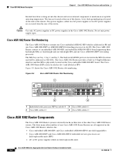
... are operational. Chapter 8 Cisco ASR 1002 Router Overview and Installation Cisco ASR 1002 Router Power Supplies Figure 8-26 shows the -48 VDC power supply for the Cisco ASR 1002 Router 12 34 5 6 0 OUTPUT INPUT FAN FAIL OK OK This unit might have more than one power supply connection. OUTPUT INPUT FAN FAIL OK OK This unit might have more than one power supply connection. Figure 8-26 -48 VDC Power Supply for the Cisco ASR 1002 Router.
... are operational. Chapter 8 Cisco ASR 1002 Router Overview and Installation Cisco ASR 1002 Router Power Supplies Figure 8-26 shows the -48 VDC power supply for the Cisco ASR 1002 Router 12 34 5 6 0 OUTPUT INPUT FAN FAIL OK OK This unit might have more than one power supply connection. OUTPUT INPUT FAN FAIL OK OK This unit might have more than one power supply connection. Figure 8-26 -48 VDC Power Supply for the Cisco ASR 1002 Router.


