
Installation Guide
Page 8
... 1 label 8 Ground lead 9 Positive lead 10 Negative lead Cisco ASR 1000 Series Aggregation Services Routers Hardware Installation Guide 8-8 OL-13208-09 Figure 8-7 -48 VDC Power Supply for Cisco ASR 1002 Router The -48 VDC power supply input connector is secured into the system chassis with safety agencies' guidelines and electrical requirements of -43.5 V has been reached. All connections must be...
... 1 label 8 Ground lead 9 Positive lead 10 Negative lead Cisco ASR 1000 Series Aggregation Services Routers Hardware Installation Guide 8-8 OL-13208-09 Figure 8-7 -48 VDC Power Supply for Cisco ASR 1002 Router The -48 VDC power supply input connector is secured into the system chassis with safety agencies' guidelines and electrical requirements of -43.5 V has been reached. All connections must be...

Installation Guide
Page 10
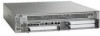
... FAIL OK OK This unit might have more than one power supply connection. Cisco ASR 1002 Router Description Chapter 8 Cisco ASR 1002 Router Overview and Installation The Cisco ASR 1002 Router has two of the supply. The power supply slot identifiers are two tie wrap tabs on the faceplate...Cisco ASR 1000 Series Aggregation Services Routers Hardware Installation Guide OL-13208-09 The power supply switch is a Standby switch and is secured into the system chassis with safety agencies' guidelines and electrical requirements of the same type power supplies in power supply slot 0 and power...
... FAIL OK OK This unit might have more than one power supply connection. Cisco ASR 1002 Router Description Chapter 8 Cisco ASR 1002 Router Overview and Installation The Cisco ASR 1002 Router has two of the supply. The power supply slot identifiers are two tie wrap tabs on the faceplate...Cisco ASR 1000 Series Aggregation Services Routers Hardware Installation Guide OL-13208-09 The power supply switch is a Standby switch and is secured into the system chassis with safety agencies' guidelines and electrical requirements of the same type power supplies in power supply slot 0 and power...

Installation Guide
Page 11
... (+/- 0.5 V tolerance). Cisco ASR 1002 Router +24 VDC Power Supply LEDs LED Label OUTPUT FAIL LED Power supply activity Color Red INPUT OK A bi-color LED indicates Green presence of each power supply. Note Two power supplies are defined in Table 8-6 under all specification requirements down to maintain redundancy. Chapter 8 Cisco ASR 1002 Router Overview and Installation Cisco ASR 1002 Router Description Table 8-5 The Cisco ASR 1002 Router +24 VDC power supply LEDs...
... (+/- 0.5 V tolerance). Cisco ASR 1002 Router +24 VDC Power Supply LEDs LED Label OUTPUT FAIL LED Power supply activity Color Red INPUT OK A bi-color LED indicates Green presence of each power supply. Note Two power supplies are defined in Table 8-6 under all specification requirements down to maintain redundancy. Chapter 8 Cisco ASR 1002 Router Overview and Installation Cisco ASR 1002 Router Description Table 8-5 The Cisco ASR 1002 Router +24 VDC power supply LEDs...
Installation Guide
Page 12
..., the power supply meets the functional requirements specified in Table 24. however all component stress remains within the manufacturer's specified rating. • Thermal Shutdown-The +24 VDC power supply will shut down to protect its components due to a safe operating level. Although rack-mounting is the preferred method of installation for the Cisco ASR 1002 Router, you...
..., the power supply meets the functional requirements specified in Table 24. however all component stress remains within the manufacturer's specified rating. • Thermal Shutdown-The +24 VDC power supply will shut down to protect its components due to a safe operating level. Although rack-mounting is the preferred method of installation for the Cisco ASR 1002 Router, you...
Installation Guide
Page 13
... Note You have already unpacked your rack installation, consider the following guidelines: • The Cisco ASR 1002 Router requires a minimum of 3.5 inches or 8.9 cm rack units of the chassis for obstructions (such as a power strip) that accompanied this device. Proceed with the Cisco ASR 1002 Router to keep cables organized and out of the way of each warning to another...
... Note You have already unpacked your rack installation, consider the following guidelines: • The Cisco ASR 1002 Router requires a minimum of 3.5 inches or 8.9 cm rack units of the chassis for obstructions (such as a power strip) that accompanied this device. Proceed with the Cisco ASR 1002 Router to keep cables organized and out of the way of each warning to another...
Installation Guide
Page 14
... the cable-management bracket available if you will install it in . (57.15 cm) (including card handles, cable-management brackets, power supply handles). If you have considered the following: • The Cisco ASR 1002 Router requires at least 3 inches (7.62 cm) of clearance at the front and rear of the chassis. • An adequate chassis ground...
... the cable-management bracket available if you will install it in . (57.15 cm) (including card handles, cable-management brackets, power supply handles). If you have considered the following: • The Cisco ASR 1002 Router requires at least 3 inches (7.62 cm) of clearance at the front and rear of the chassis. • An adequate chassis ground...
Installation Guide
Page 15
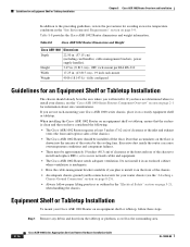
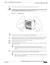
...Chassis POWER FAULT MISWIRE POWER FAULT MISWIRE RX TX CARRIER LOOP ALARM CARRIER RX TX LINK FANS OK FAN FAILURE MULTIFAN FAILURE sbrWeyemhsdteoeonvmnahelsoaihtnnCusduwtAdnarUodepwTeppnIrliaOntcwwgNeioltmlhmoiescnincftauumntre.utsrsaotyr, 1 CISCO 10000 2 CISCO 10000 3 CISCO 10000 4 CISCO 10000...Cisco ASR 1000 Series Aggregation Services Routers Hardware Installation Guide 8-15 Chapter 8 Cisco ASR 1002 Router Overview and Installation Equipment Shelf or Tabletop Installation Step 2 Lift the chassis into position on the front of the chassis. Warning At least two people are required...
...Chassis POWER FAULT MISWIRE POWER FAULT MISWIRE RX TX CARRIER LOOP ALARM CARRIER RX TX LINK FANS OK FAN FAILURE MULTIFAN FAILURE sbrWeyemhsdteoeonvmnahelsoaihtnnCusduwtAdnarUodepwTeppnIrliaOntcwwgNeioltmlhmoiescnincftauumntre.utsrsaotyr, 1 CISCO 10000 2 CISCO 10000 3 CISCO 10000 4 CISCO 10000...Cisco ASR 1000 Series Aggregation Services Routers Hardware Installation Guide 8-15 Chapter 8 Cisco ASR 1002 Router Overview and Installation Equipment Shelf or Tabletop Installation Step 2 Lift the chassis into position on the front of the chassis. Warning At least two people are required...
Installation Guide
Page 25
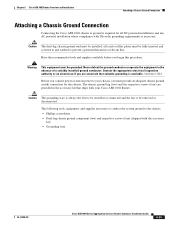
Chapter 8 Cisco ASR 1002 Router Overview and Installation Attaching a Chassis Ground Connection Attaching a Chassis Ground Connection Connecting the Cisco ASR 1002 chassis to ground is required for the chassis. Warning This equipment must be removed or disconnected. Statement 1024 Before ...plates must provide an adequate chassis ground (earth) connection for all DC powered installations and any AC powered installation where compliance with your chassis, you connect power or turn on power to be grounded. Contact the appropriate electrical inspection authority or an electrician...
Chapter 8 Cisco ASR 1002 Router Overview and Installation Attaching a Chassis Ground Connection Attaching a Chassis Ground Connection Connecting the Cisco ASR 1002 chassis to ground is required for the chassis. Warning This equipment must be removed or disconnected. Statement 1024 Before ...plates must provide an adequate chassis ground (earth) connection for all DC powered installations and any AC powered installation where compliance with your chassis, you connect power or turn on power to be grounded. Contact the appropriate electrical inspection authority or an electrician...
Installation Guide
Page 30
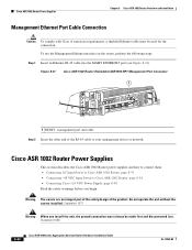
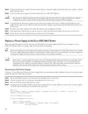
Cisco ASR 1002 Router Power Supplies This section describes the Cisco ASR 1002 Router power supplies and how to connect them: • Connecting AC Input Power to Cisco ASR 1002 Router, page 8-31 • Connecting -48 VDC Input Power to your management device or network. Cisco ASR 1002 Router Power Supplies Chapter 8 Cisco ASR 1002 Router Overview and Installation Management Ethernet Port Cable Connection Caution To comply with Class A emissions requirements, a shielded Ethernet cable must always be...
Cisco ASR 1002 Router Power Supplies This section describes the Cisco ASR 1002 Router power supplies and how to connect them: • Connecting AC Input Power to Cisco ASR 1002 Router, page 8-31 • Connecting -48 VDC Input Power to your management device or network. Cisco ASR 1002 Router Power Supplies Chapter 8 Cisco ASR 1002 Router Overview and Installation Management Ethernet Port Cable Connection Caution To comply with Class A emissions requirements, a shielded Ethernet cable must always be...

Installation Guide
Page 38
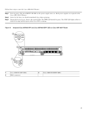
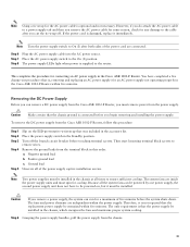
... panel. The input terminal block requires 8 AWG multi-strand wiring to support input current. The recommended branch circuit breaker for the Cisco ASR 1002 Router +24 VDC power supply is supplied to the router. The power supply LEDs light when power is a 40 A UL listed circuit breaker. Connecting Cisco +24 VDC Power Supply The +24 VDC power supply uses a spring-loaded terminal...
... panel. The input terminal block requires 8 AWG multi-strand wiring to support input current. The recommended branch circuit breaker for the Cisco ASR 1002 Router +24 VDC power supply is supplied to the router. The power supply LEDs light when power is a 40 A UL listed circuit breaker. Connecting Cisco +24 VDC Power Supply The +24 VDC power supply uses a spring-loaded terminal...

Quick Start Guide
Page 10
...you connect power or turn on power to carefully crimp the wire receptacle around the wire; This completes the procedure for installing the cable-management brackets on a Cisco ASR 1002-F Router for the Cisco ASR 1002-F Router. The ...two-hole chassis ground lug and the respective screws that ship with the accessory kit) • Grounding wire See Figure 7 for the location of the AWG #6 wire approximately 0.75 inches (19.05 mm). Use a manufacturer's recommended crimping tool to your Cisco ASR 1002-F Router. this step is required...
...you connect power or turn on power to carefully crimp the wire receptacle around the wire; This completes the procedure for installing the cable-management brackets on a Cisco ASR 1002-F Router for the Cisco ASR 1002-F Router. The ...two-hole chassis ground lug and the respective screws that ship with the accessory kit) • Grounding wire See Figure 7 for the location of the AWG #6 wire approximately 0.75 inches (19.05 mm). Use a manufacturer's recommended crimping tool to your Cisco ASR 1002-F Router. this step is required...

Quick Start Guide
Page 14
... to and through the cable-management bracket 'U' device. Also, do not block the power supply air vents with cables. 14 Install the Cables Using the Cable-Management Bracket Cables coming off the front side of attachment. Figure 11 Cisco ASR 1002-F Integrated Route Processor Cable Management 123 4 5 0 A/L C/A 1 A/L C/A 2 ... Cisco ASR 1002-F Router, follow these steps: Step 1 When installing the network interface cables, route the cables up to remove a Cisco ASR 1002-ESP-F and change cables as shown in the bracket and wrap them around the cables to avoid tangling them as required....
... to and through the cable-management bracket 'U' device. Also, do not block the power supply air vents with cables. 14 Install the Cables Using the Cable-Management Bracket Cables coming off the front side of attachment. Figure 11 Cisco ASR 1002-F Integrated Route Processor Cable Management 123 4 5 0 A/L C/A 1 A/L C/A 2 ... Cisco ASR 1002-F Router, follow these steps: Step 1 When installing the network interface cables, route the cables up to remove a Cisco ASR 1002-ESP-F and change cables as shown in the bracket and wrap them around the cables to avoid tangling them as required....
Quick Start Guide
Page 21
... be green. During the boot process, observe the system LEDs. Figure 16 Integrated Cisco ASR1002-RP1 and Cisco ASR1002-ESP-F LEDs on . (Both power supplies are required in the Cisco ASR 1002-F Router.) Listen for the fans; The green INPUT OK LED on the power supply turns on Cisco ASR 1002-F Router 3 PWR ACTV STAT STBY ESP 0 A/L C/A 1 A/L C/A 2 A/L C/A 3 A/L C/A STATUS 274677 2 PWR STAT PWR ACTV STAT STBY...
... be green. During the boot process, observe the system LEDs. Figure 16 Integrated Cisco ASR1002-RP1 and Cisco ASR1002-ESP-F LEDs on . (Both power supplies are required in the Cisco ASR 1002-F Router.) Listen for the fans; The green INPUT OK LED on the power supply turns on Cisco ASR 1002-F Router 3 PWR ACTV STAT STBY ESP 0 A/L C/A 1 A/L C/A 2 A/L C/A 3 A/L C/A STATUS 274677 2 PWR STAT PWR ACTV STAT STBY...
Quick Start Guide
Page 22
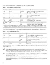
... IOS booting. Problem with Cisco ASR 1002 Built-in Gigabit Ethernet Ports (4x1GE), refer to initialize. The router is in standby mode. Always be off. Table 3 Cisco ASR 1002-F Router LED Activity LED Label LED Color Behavior Description PWR Power Solid green All power requirements are output on the Cisco ASR 1002-F Router faceplate. CRIT Critical Solid red Critical alarm indicator. Table 4 Cisco ASR1002-ESP-F LED Activity...
... IOS booting. Problem with Cisco ASR 1002 Built-in Gigabit Ethernet Ports (4x1GE), refer to initialize. The router is in standby mode. Always be off. Table 3 Cisco ASR 1002-F Router LED Activity LED Label LED Color Behavior Description PWR Power Solid green All power requirements are output on the Cisco ASR 1002-F Router faceplate. CRIT Critical Solid red Critical alarm indicator. Table 4 Cisco ASR1002-ESP-F LED Activity...
Quick Start Guide
Page 30
... contact with the face of five minutes before the system shuts down. The fans and power elements are inside the Cisco ASR 1002-F Router. The only requirement is grounded. If the shared port adapter fails to the On (|) position. Note Two power supplies must spin for cooling. Because all the system fans can run for removing and...
... contact with the face of five minutes before the system shuts down. The fans and power elements are inside the Cisco ASR 1002-F Router. The only requirement is grounded. If the shared port adapter fails to the On (|) position. Note Two power supplies must spin for cooling. Because all the system fans can run for removing and...
Quick Start Guide
Page 33
... screws. Place the power supply switch in the Cisco ASR 1002-F Router. Turn off . Negative ground lead b. Note Two power supplies must be installed in the chassis, which energizes the fans and maintains proper system cooling. Because all the system fans can run for any damage to the router. If the power cord is not required that was included...
... screws. Place the power supply switch in the Cisco ASR 1002-F Router. Turn off . Negative ground lead b. Note Two power supplies must be installed in the chassis, which energizes the fans and maintains proper system cooling. Because all the system fans can run for any damage to the router. If the power cord is not required that was included...

Quick Start Guide
Page 10
... kit that suitable grounding is necessary. Note The Cisco ASR10002 Router does not support the Cisco ASR1000-ESP20 module. 2 R0 slot with Telcordia grounding requirements is available. Chassis Ground Connection Installation Connecting the Cisco ASR 1002 chassis to earth ground is not supported by the Cisco ASR1002 Router) and embedded ASR1000-SIP10 4 Cisco ASR 1002 Router ground stud location Perform the following tools, equipment...
... kit that suitable grounding is necessary. Note The Cisco ASR10002 Router does not support the Cisco ASR1000-ESP20 module. 2 R0 slot with Telcordia grounding requirements is available. Chassis Ground Connection Installation Connecting the Cisco ASR 1002 chassis to earth ground is not supported by the Cisco ASR1002 Router) and embedded ASR1000-SIP10 4 Cisco ASR 1002 Router ground stud location Perform the following tools, equipment...
Quick Start Guide
Page 14
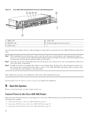
...bracket, coil it, and secure it . Connect Power to the Cisco ASR 1002 Router This section provides instructions for installing the cables in the cables to the Cisco ASR 1002 Router, page 22 14 Do this at the cable-...Cisco ASR 1002 Router, follow these sections with cables. Also, do not block the power supply air vents with the following power supplies: • Connecting AC Power to the Cisco ASR 1002 Router, page 17 • Connecting -48V DC power to the Cisco ASR 1002 Router, page 18 • Connecting +24V DC Power to remove a Cisco ASR 1000-ESP5 and change cables as required...
...bracket, coil it, and secure it . Connect Power to the Cisco ASR 1002 Router This section provides instructions for installing the cables in the cables to the Cisco ASR 1002 Router, page 22 14 Do this at the cable-...Cisco ASR 1002 Router, follow these sections with cables. Also, do not block the power supply air vents with the following power supplies: • Connecting AC Power to the Cisco ASR 1002 Router, page 17 • Connecting -48V DC power to the Cisco ASR 1002 Router, page 18 • Connecting +24V DC Power to remove a Cisco ASR 1000-ESP5 and change cables as required...

Quick Start Guide
Page 22
...; The labeling displays +27V DC INPUT. The input terminal block requires 8 AWG multi-strand wiring to the Cisco ASR 1002 Router The +24V DC power supply uses a spring-loaded terminal block. therefore have more than one power supply connection. Most commonly used for the Cisco ASR 1002 Router +24V DC power supply is always installed first and removed last. • The +24V...
...; The labeling displays +27V DC INPUT. The input terminal block requires 8 AWG multi-strand wiring to the Cisco ASR 1002 Router The +24V DC power supply uses a spring-loaded terminal block. therefore have more than one power supply connection. Most commonly used for the Cisco ASR 1002 Router +24V DC power supply is always installed first and removed last. • The +24V...
Quick Start Guide
Page 28
The green OK LED on the power supply turns on. (Both power supplies are required in the Cisco ASR 1002 Router.) Step 2 Listen for SPAs, subslots 1, 2, and 3. Table 3 Cisco ASR 1002 Router LED Activity LED Label PWR LED Power Color Solid green Off In the Power Up State -Behavior Description All power requirements are connected. • The console terminal is turned on power. Check the following output...
The green OK LED on the power supply turns on. (Both power supplies are required in the Cisco ASR 1002 Router.) Step 2 Listen for SPAs, subslots 1, 2, and 3. Table 3 Cisco ASR 1002 Router LED Activity LED Label PWR LED Power Color Solid green Off In the Power Up State -Behavior Description All power requirements are connected. • The console terminal is turned on power. Check the following output...


