Hardware Installation Guide
Page 5
... Lightweight Access Points 5-2 LED Indications 5-3 Power Injector 5-4 Checking Power 5-5 Using DHCP Option 43 5-5 Manually Configuring Controller Information Using the Access Point CLI 5-6 Connecting to the Console Serial Port 5-6 Configuring Controller Information 5-7 Clearing Manually Entered Controller Information 5-7 Manually Resetting the Access Point to Defaults 5-8 Returning the Access Point to Autonomous Mode 5-8 Using a Controller to Return the Access Point to Autonomous Mode 5-8 Cisco Aironet 1300 Series Wireless Outdoor Access Point/Bridge...
... Lightweight Access Points 5-2 LED Indications 5-3 Power Injector 5-4 Checking Power 5-5 Using DHCP Option 43 5-5 Manually Configuring Controller Information Using the Access Point CLI 5-6 Connecting to the Console Serial Port 5-6 Configuring Controller Information 5-7 Clearing Manually Entered Controller Information 5-7 Manually Resetting the Access Point to Defaults 5-8 Returning the Access Point to Autonomous Mode 5-8 Using a Controller to Return the Access Point to Autonomous Mode 5-8 Cisco Aironet 1300 Series Wireless Outdoor Access Point/Bridge...
Hardware Installation Guide
Page 10
... features used during setup of lightweightaccess points. Appendix G, "Configuring DHCP Option 43 for lightweight access points. Cisco Aironet 1300 Series Wireless Outdoor Access Point/Bridge Hardware Installation Guide x OL-5048-06 Appendix F, "Priming Lightweight Access Points Prior to Deployment," describes the procedure to configure DHCP Option 43 for Lightweight Access Points," describes the procedure to prime lightweight access points with controller information. Caution Means reader...
... features used during setup of lightweightaccess points. Appendix G, "Configuring DHCP Option 43 for lightweight access points. Cisco Aironet 1300 Series Wireless Outdoor Access Point/Bridge Hardware Installation Guide x OL-5048-06 Appendix F, "Priming Lightweight Access Points Prior to Deployment," describes the procedure to configure DHCP Option 43 for Lightweight Access Points," describes the procedure to prime lightweight access points with controller information. Caution Means reader...
Hardware Installation Guide
Page 17
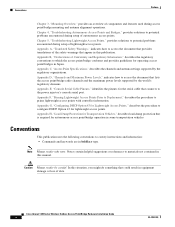
...: +32 2 704 55 55 USA: 1 800 553 2447 OL-5048-06 Cisco Aironet 1300 Series Wireless Outdoor Access Point/Bridge Hardware Installation Guide xvii Submitting a Service Request Using the online TAC Service Request Tool is the fastest way to Figure 2). Preface Obtaining Technical Assistance The power injector serial number is located on the bottom of the cabinet (refer...
...: +32 2 704 55 55 USA: 1 800 553 2447 OL-5048-06 Cisco Aironet 1300 Series Wireless Outdoor Access Point/Bridge Hardware Installation Guide xvii Submitting a Service Request Using the online TAC Service Request Tool is the fastest way to Figure 2). Preface Obtaining Technical Assistance The power injector serial number is located on the bottom of the cabinet (refer...
Hardware Installation Guide
Page 23
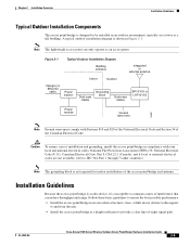
...; Enclosure supports indoor or outdoor installations • Dual-coax 100-Mbps Ethernet ports • Four LEDs • Inline power over dual-coax cables • Console serial interface on power injector • Integrated antenna or external antenna configurations (see Figure 1-1) The autonomous access point/bridge supports these additional key features: • Centralized control using Cisco IOS commands, Internet browser...
...; Enclosure supports indoor or outdoor installations • Dual-coax 100-Mbps Ethernet ports • Four LEDs • Inline power over dual-coax cables • Console serial interface on power injector • Integrated antenna or external antenna configurations (see Figure 1-1) The autonomous access point/bridge supports these additional key features: • Centralized control using Cisco IOS commands, Internet browser...
Hardware Installation Guide
Page 24
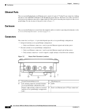
... be purchased. Power The access point/bridge receives inline power from the power injector to the access point/bridge. Key Features Figure 1-1 shows the two outdoor access point/bridge configurations. Dual-coax cables are available only on the external antenna access point/bridge configuration. The power injector is an external unit designed for operation in two models: • Cisco Aironet Power Injector LR2-standard version (included with the access point/bridge) Cisco Aironet 1300 Series Wireless Outdoor Access Point/Bridge Hardware Installation...
... be purchased. Power The access point/bridge receives inline power from the power injector to the access point/bridge. Key Features Figure 1-1 shows the two outdoor access point/bridge configurations. Dual-coax cables are available only on the external antenna access point/bridge configuration. The power injector is an external unit designed for operation in two models: • Cisco Aironet Power Injector LR2-standard version (included with the access point/bridge) Cisco Aironet 1300 Series Wireless Outdoor Access Point/Bridge Hardware Installation...
Hardware Installation Guide
Page 25
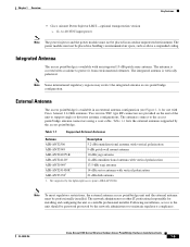
... the external antennas supported by the lightweight access point (AIR-LAP1310G) Note To meet regulatory restrictions, the external antenna access point/bridge unit and the external antenna must not be professionally installed. OL-5048-06 Cisco Aironet 1300 Series Wireless Outdoor Access Point/Bridge Hardware Installation Guide 1-5 Not supported by the access point/bridge. Chapter 1 Overview Key Features • Cisco Aironet Power Injector LR2T-optional transportation version - 12- Note...
... the external antennas supported by the lightweight access point (AIR-LAP1310G) Note To meet regulatory restrictions, the external antenna access point/bridge unit and the external antenna must not be professionally installed. OL-5048-06 Cisco Aironet 1300 Series Wireless Outdoor Access Point/Bridge Hardware Installation Guide 1-5 Not supported by the access point/bridge. Chapter 1 Overview Key Features • Cisco Aironet Power Injector LR2T-optional transportation version - 12- Note...
Hardware Installation Guide
Page 26
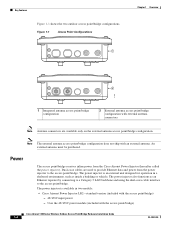
... inline 48-VDC power from the power injector to support a single antenna or dual-diversity antennas Figure 1-2 Access Point Connector Locations 117060 1 2 3 4 5 1 Ground lug mounting screws 3 Mounting posts 2 Left antenna connector (external antenna 4 LEDs access point/bridge configuration only) Primary right antenna connector (external antenna access point/bridge configuration only) 5 Dual-coax Ethernet ports (F-Type connectors) Cisco Aironet 1300 Series Wireless Outdoor Access Point/Bridge Hardware Installation...
... inline 48-VDC power from the power injector to support a single antenna or dual-diversity antennas Figure 1-2 Access Point Connector Locations 117060 1 2 3 4 5 1 Ground lug mounting screws 3 Mounting posts 2 Left antenna connector (external antenna 4 LEDs access point/bridge configuration only) Primary right antenna connector (external antenna access point/bridge configuration only) 5 Dual-coax Ethernet ports (F-Type connectors) Cisco Aironet 1300 Series Wireless Outdoor Access Point/Bridge Hardware Installation...
Hardware Installation Guide
Page 37
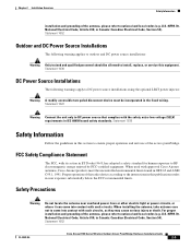
Statement 1052 Outdoor and DC Power Source Installations The following warnings apply to DC power source installations using the optional LR2T power injector: Warning A readily accessible two-poled disconnect device must be ...Cisco Aironet 1300 Series Wireless Outdoor Access Point/Bridge Hardware Installation Guide 2-3 For proper installation and grounding of the access point/bridge. U.S.:NFPA 70, National Electrical Code, Article 810, in Canada: Canadian Electrical Code, Section 54). Statement 1030 DC Power Source Installations The following warning applies to outdoor and DC power...
Statement 1052 Outdoor and DC Power Source Installations The following warnings apply to DC power source installations using the optional LR2T power injector: Warning A readily accessible two-poled disconnect device must be ...Cisco Aironet 1300 Series Wireless Outdoor Access Point/Bridge Hardware Installation Guide 2-3 For proper installation and grounding of the access point/bridge. U.S.:NFPA 70, National Electrical Code, Article 810, in Canada: Canadian Electrical Code, Section 54). Statement 1030 DC Power Source Installations The following warning applies to outdoor and DC power...
Hardware Installation Guide
Page 39
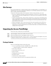
... grounding, install the access point/bridge in Figure 2-1. Installation Guidelines Because the access point/bridge is a radio device, it is not required for indoor installations of the access point/bridge and antenna. Figure 2-1 Typical Outdoor Installation Diagram Building entrance Integrated or external antenna Indoor Outdoor Category 5 Ethernet cable Power injector Dual-coax cables Grounding block Dual-coax cables BR1310G or LAP1310G Power module Ground (see...
... grounding, install the access point/bridge in Figure 2-1. Installation Guidelines Because the access point/bridge is a radio device, it is not required for indoor installations of the access point/bridge and antenna. Figure 2-1 Typical Outdoor Installation Diagram Building entrance Integrated or external antenna Indoor Outdoor Category 5 Ethernet cable Power injector Dual-coax cables Grounding block Dual-coax cables BR1310G or LAP1310G Power module Ground (see...
Hardware Installation Guide
Page 40
...Power injector (LR2) unit • Power module and AC power cord • Quick start guide • Mounting instructions document • Read Me document • Translated safety warnings document • Cisco product registration and Cisco documentation feedback cards Cisco Aironet 1300 Series Wireless Outdoor Access Point/Bridge...antenna configuration is damaged or missing, notify your authorized Cisco sales representative. Unpacking the Access Point/Bridge Follow these items: • An access point/bridge unit (model: AIR-BR1310G or AIR-LAP1310G) - The maximum radio range is an ...
...Power injector (LR2) unit • Power module and AC power cord • Quick start guide • Mounting instructions document • Read Me document • Translated safety warnings document • Cisco product registration and Cisco documentation feedback cards Cisco Aironet 1300 Series Wireless Outdoor Access Point/Bridge...antenna configuration is damaged or missing, notify your authorized Cisco sales representative. Unpacking the Access Point/Bridge Follow these items: • An access point/bridge unit (model: AIR-BR1310G or AIR-LAP1310G) - The maximum radio range is an ...
Hardware Installation Guide
Page 41
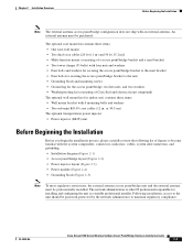
... (Figure 2-1) • Access point/bridge layout (Figure 2-2) • Power injector layout (Figure 2-3) • Power module (Figure 2-4) • Grounding block (Figure 2-5) Note To meet regulatory restrictions, the external antenna access point/bridge unit and the external antenna... installation, access to maintain regulatory compliance. OL-5048-06 Cisco Aironet 1300 Series Wireless Outdoor Access Point/Bridge Hardware Installation Guide 2-7 Chapter 2 Installation Overview Before Beginning the Installation Note The external antenna access point/bridge configuration does...
... (Figure 2-1) • Access point/bridge layout (Figure 2-2) • Power injector layout (Figure 2-3) • Power module (Figure 2-4) • Grounding block (Figure 2-5) Note To meet regulatory restrictions, the external antenna access point/bridge unit and the external antenna... installation, access to maintain regulatory compliance. OL-5048-06 Cisco Aironet 1300 Series Wireless Outdoor Access Point/Bridge Hardware Installation Guide 2-7 Chapter 2 Installation Overview Before Beginning the Installation Note The external antenna access point/bridge configuration does...
Hardware Installation Guide
Page 42
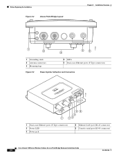
... 2-2 Access Point/Bridge Layout Chapter 2 Installation Overview 117060 1 2 3 4 5 1 Grounding studs 2 Antenna connectors 3 Mounting lugs 4 LEDs 5 Dual-coax Ethernet ports (F-Type connectors) Figure 2-3 Power Injector Indicators and Connectors CISCPOOWAERIRINOJENCTEORT 117189 45 3 1 12 1 Dual-coax Ethernet ports (F-Type connectors) 2 Power LED 3 Power jack 4 Ethernet LAN port (RJ-45 connector) 5 Console serial port (RJ-45 connector) Cisco Aironet 1300 Series Wireless Outdoor Access Point/Bridge Hardware...
... 2-2 Access Point/Bridge Layout Chapter 2 Installation Overview 117060 1 2 3 4 5 1 Grounding studs 2 Antenna connectors 3 Mounting lugs 4 LEDs 5 Dual-coax Ethernet ports (F-Type connectors) Figure 2-3 Power Injector Indicators and Connectors CISCPOOWAERIRINOJENCTEORT 117189 45 3 1 12 1 Dual-coax Ethernet ports (F-Type connectors) 2 Power LED 3 Power jack 4 Ethernet LAN port (RJ-45 connector) 5 Console serial port (RJ-45 connector) Cisco Aironet 1300 Series Wireless Outdoor Access Point/Bridge Hardware...
Hardware Installation Guide
Page 43
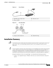
... 2-5 1 Grounding Block 12 3 AC power cord 88830 1 F-type coaxial connectors Installation Summary 2 Ground wire lug Caution You should be password-protected by incorrect power application. The network administrator or other IT professional responsible for installing and configuring the unit is a suitable professional installer. OL-5048-06 Cisco Aironet 1300 Series Wireless Outdoor Access Point/Bridge Hardware Installation Guide 2-9
... 2-5 1 Grounding Block 12 3 AC power cord 88830 1 F-type coaxial connectors Installation Summary 2 Ground wire lug Caution You should be password-protected by incorrect power application. The network administrator or other IT professional responsible for installing and configuring the unit is a suitable professional installer. OL-5048-06 Cisco Aironet 1300 Series Wireless Outdoor Access Point/Bridge Hardware Installation Guide 2-9
Hardware Installation Guide
Page 44
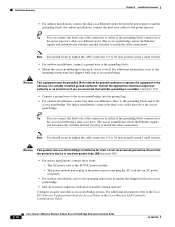
...Access Points or the Cisco Wireless LAN Controller Configuration Guide. 2-10 Cisco Aironet 1300 Series Wireless Outdoor Access Point/Bridge Hardware Installation Guide OL-5048-06 Ensure that shipped with special weather sealing material. Note You should securely tighten the cable connectors (15 to 20 inch-pounds) using a small wrench. The AC power cord to the access point/bridge... the access point/bridge (use the ground lug). • For outdoor installations, connect the dual-coax Ethernet cables to the grounding block and to the power injector. The access point/bridge senses ...
...Access Points or the Cisco Wireless LAN Controller Configuration Guide. 2-10 Cisco Aironet 1300 Series Wireless Outdoor Access Point/Bridge Hardware Installation Guide OL-5048-06 Ensure that shipped with special weather sealing material. Note You should securely tighten the cable connectors (15 to 20 inch-pounds) using a small wrench. The AC power cord to the access point/bridge... the access point/bridge (use the ground lug). • For outdoor installations, connect the dual-coax Ethernet cables to the grounding block and to the power injector. The access point/bridge senses ...
Hardware Installation Guide
Page 47
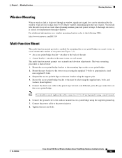
..., or a roof mount and consists of two parts (see Figure 3-1): • An access point/bridge bracket-attaches to the back of glass. OL-5048-06 Cisco Aironet 1300 Series Wireless Outdoor Access Point/Bridge Hardware Installation Guide 3-3 A thorough site survey is critical for mounting the access point/bridge on the access point/bridge. 2. Tighten the nuts and bolts. Typical losses range from 5 to15 dB per...
..., or a roof mount and consists of two parts (see Figure 3-1): • An access point/bridge bracket-attaches to the back of glass. OL-5048-06 Cisco Aironet 1300 Series Wireless Outdoor Access Point/Bridge Hardware Installation Guide 3-3 A thorough site survey is critical for mounting the access point/bridge on the access point/bridge. 2. Tighten the nuts and bolts. Typical losses range from 5 to15 dB per...
Hardware Installation Guide
Page 50
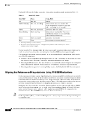
... depends on the access point/bridge configuration, which can align the integrated antenna using LEDs after association, the unit reads the receive signal strength indictor (RSSI) levels and records the maximum level received. If the unit associates to determine when the bridge successfully associates with a root bridge for 60 seconds1. Cisco Aironet 1300 Series Wireless Outdoor Access Point/Bridge Hardware Installation...
... depends on the access point/bridge configuration, which can align the integrated antenna using LEDs after association, the unit reads the receive signal strength indictor (RSSI) levels and records the maximum level received. If the unit associates to determine when the bridge successfully associates with a root bridge for 60 seconds1. Cisco Aironet 1300 Series Wireless Outdoor Access Point/Bridge Hardware Installation...
Hardware Installation Guide
Page 53
... • Obtaining the Autonomous Access Point/Bridge Image File, page 4-13 • Connecting to the Console Serial Port, page 4-14 • Obtaining the TFTP Server Software, page 4-15 OL-5048-06 Cisco Aironet 1300 Series Wireless Outdoor Access Point/Bridge Hardware Installation Guide 4-1 CH A P T E R 4 Troubleshooting Autonomous Access Points and Bridges This chapter provides troubleshooting procedures for basic problems with the autonomous access point/bridge (model: AIR-BR1310G).
... • Obtaining the Autonomous Access Point/Bridge Image File, page 4-13 • Connecting to the Console Serial Port, page 4-14 • Obtaining the TFTP Server Software, page 4-15 OL-5048-06 Cisco Aironet 1300 Series Wireless Outdoor Access Point/Bridge Hardware Installation Guide 4-1 CH A P T E R 4 Troubleshooting Autonomous Access Points and Bridges This chapter provides troubleshooting procedures for basic problems with the autonomous access point/bridge (model: AIR-BR1310G).
Hardware Installation Guide
Page 54
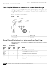
...power injector power jack. Figure 4-1 LEDs RSE I 117061 R Radio LED S Status LED E Ethernet LED I Install LED Normal Mode LED Indications for assistance. LED Indications Status LED - - You can use them to the "LEDs" section on the back panel. Cisco Aironet 1300 Series Wireless Outdoor Access Point/Bridge... Hardware Installation Guide 4-2 OL-5048-06 Meaning Ethernet link is not associating with a remote bridge or a wireless client, check the four LEDs on page...
...power injector power jack. Figure 4-1 LEDs RSE I 117061 R Radio LED S Status LED E Ethernet LED I Install LED Normal Mode LED Indications for assistance. LED Indications Status LED - - You can use them to the "LEDs" section on the back panel. Cisco Aironet 1300 Series Wireless Outdoor Access Point/Bridge... Hardware Installation Guide 4-2 OL-5048-06 Meaning Ethernet link is not associating with a remote bridge or a wireless client, check the four LEDs on page...
Hardware Installation Guide
Page 55
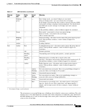
... Cisco Aironet 1300 Series Wireless Outdoor Access Point/Bridge Hardware Installation Guide 4-3 Green - - - green - - Meaning Root bridge mode-no remote bridges are powered up, this could be caused by the LED flashing red to associate with a root bridge for...power to associate with a non-root bridge indefinitely. Blinking - Preconfigured bridges search indefinitely. This is normal operation. Maximum retries or buffer full occurred on an Autonomous Access Point/Bridge Table 4-1 Ethernet LED - The access point/bridge attempts to the power injector, check all bridges...
... Cisco Aironet 1300 Series Wireless Outdoor Access Point/Bridge Hardware Installation Guide 4-3 Green - - - green - - Meaning Root bridge mode-no remote bridges are powered up, this could be caused by the LED flashing red to associate with a root bridge for...power to associate with a non-root bridge indefinitely. Blinking - Preconfigured bridges search indefinitely. This is normal operation. Maximum retries or buffer full occurred on an Autonomous Access Point/Bridge Table 4-1 Ethernet LED - The access point/bridge attempts to the power injector, check all bridges...

Hardware Installation Guide
Page 57
... to 40 VDC from a vehicle battery OL-5048-06 Cisco Aironet 1300 Series Wireless Outdoor Access Point/Bridge Hardware Installation Guide 4-5 When power is powered up, it applies 48-VDC to the dual-coax cables to the access point/bridge. Figure 4-2 Power Injector CISCPOOWAERIRINOJENCTEORT 117189 45 3 1 12 1 Dual-coax Ethernet ports (F-Type connectors) 2 Power LED 3 Power jack 4 Ethernet LAN port (RJ-45 connector) 5 Console serial...
... to 40 VDC from a vehicle battery OL-5048-06 Cisco Aironet 1300 Series Wireless Outdoor Access Point/Bridge Hardware Installation Guide 4-5 When power is powered up, it applies 48-VDC to the dual-coax cables to the access point/bridge. Figure 4-2 Power Injector CISCPOOWAERIRINOJENCTEORT 117189 45 3 1 12 1 Dual-coax Ethernet ports (F-Type connectors) 2 Power LED 3 Power jack 4 Ethernet LAN port (RJ-45 connector) 5 Console serial...


