Hardware Installation Guide
Page 10
..."Channels and Antenna Settings," lists the access point radio channels and the maximum power levels supported by the world's regulatory domains. Interactive examples use these conventions: ... use these conventions: • Commands and keywords are in boldface text. • Arguments for which you supply values are in italic. • Square brackets ([ ]) mean optional elements. • Braces ({ }) ..., cautions, and timesavers use the web-browser interface to configure the access point. Cisco Aironet 1200 Series Access Point Hardware Installation Guide x OL-4310-05 Chapter 6, "Mounting...
..."Channels and Antenna Settings," lists the access point radio channels and the maximum power levels supported by the world's regulatory domains. Interactive examples use these conventions: ... use these conventions: • Commands and keywords are in boldface text. • Arguments for which you supply values are in italic. • Square brackets ([ ]) mean optional elements. • Braces ({ }) ..., cautions, and timesavers use the web-browser interface to configure the access point. Cisco Aironet 1200 Series Access Point Hardware Installation Guide x OL-4310-05 Chapter 6, "Mounting...
Hardware Installation Guide
Page 22
... bit and no other power injectors or power modules have been tested to Appendix E, "Console Cable Pinouts," for both 2.4-GHz and 5-GHz radios. Cisco Aironet Power Injector (AIR-PWRINJ-FIB or AIR-PWRINJ3) - Note When...air space, such as above suspended ceilings. no flow control. Power Sources The access point can receive power from an external power module or through inline power using a terminal emulator program. Other switches and patch panels might not provide enough power for a description of the console port pinouts.) Assign the following power sources: • Power supply...
... bit and no other power injectors or power modules have been tested to Appendix E, "Console Cable Pinouts," for both 2.4-GHz and 5-GHz radios. Cisco Aironet Power Injector (AIR-PWRINJ-FIB or AIR-PWRINJ3) - Note When...air space, such as above suspended ceilings. no flow control. Power Sources The access point can receive power from an external power module or through inline power using a terminal emulator program. Other switches and patch panels might not provide enough power for a description of the console port pinouts.) Assign the following power sources: • Power supply...
Hardware Installation Guide
Page 29
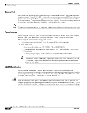
... for damage. Package Contents Each access point package contains the following items: • Cisco Aironet 1200 Series Access Point • Cisco Aironet 1200 Series Power Module (Universal power supply) • Quick Start Guide: Cisco Aironet 1200 Series Access Points • Cisco product registration and Cisco documentation feedback cards The optional 2.4-GHz radio upgrade kit is shipped with the...
... for damage. Package Contents Each access point package contains the following items: • Cisco Aironet 1200 Series Access Point • Cisco Aironet 1200 Series Power Module (Universal power supply) • Quick Start Guide: Cisco Aironet 1200 Series Access Points • Cisco product registration and Cisco documentation feedback cards The optional 2.4-GHz radio upgrade kit is shipped with the...
Hardware Installation Guide
Page 34
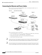
... Power cord Universal power supply 74164 Access Point Option 4 The access point power options are listed below: • A switch with inline power, such as a Cisco Catalyst 3500XL, 3550-24 PWR, 4000, or 6500 switch • A Cisco Aironet Power Injector (AIR-PWRINJ-FIB or AIR-PWRINJ3) • An inline power patch panel, such as the Cisco Catalyst Inline Power Patch Panel • A power module (Universal power supply...
... Power cord Universal power supply 74164 Access Point Option 4 The access point power options are listed below: • A switch with inline power, such as a Cisco Catalyst 3500XL, 3550-24 PWR, 4000, or 6500 switch • A Cisco Aironet Power Injector (AIR-PWRINJ-FIB or AIR-PWRINJ3) • An inline power patch panel, such as the Cisco Catalyst Inline Power Patch Panel • A power module (Universal power supply...

Hardware Installation Guide
Page 35
... point. Note If you use a power supply or power injector to power the access point, you are designed for use the power supply included with Cisco Aironet access points only. Plug the other end of a Cisco Aironet power injector labeled To AP/Bridge. Follow ...these steps to connect the access point to an Ethernet LAN when you must use with your access point and the Cisco Aironet Power Injector for operation in a building's environmental air...
... point. Note If you use a power supply or power injector to power the access point, you are designed for use the power supply included with Cisco Aironet access points only. Plug the other end of a Cisco Aironet power injector labeled To AP/Bridge. Follow ...these steps to connect the access point to an Ethernet LAN when you must use with your access point and the Cisco Aironet Power Injector for operation in a building's environmental air...
Hardware Installation Guide
Page 71
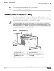
...bar box hanger 5 Bracket mounting clip 6 Access point mounting bracket 7 Access point OL-4310-05 Cisco Aironet 1200 Series Access Point Hardware Installation Guide 6-5 no other power injectors or power modules have been tested to UL 2043 and they should not be helpful to refer to allow room ...; Caution Only the fiber-optic power injector (AIR-PWRINJ-FIB) has been tested to be integrated into the T-bar grid above the top surface of a suspended ceiling. Do not overtighten. Using a T-bar box hanger and bracket mounting clip (not supplied) such as above suspended ceilings. Mounting ...
...bar box hanger 5 Bracket mounting clip 6 Access point mounting bracket 7 Access point OL-4310-05 Cisco Aironet 1200 Series Access Point Hardware Installation Guide 6-5 no other power injectors or power modules have been tested to UL 2043 and they should not be helpful to refer to allow room ...; Caution Only the fiber-optic power injector (AIR-PWRINJ-FIB) has been tested to be integrated into the T-bar grid above the top surface of a suspended ceiling. Do not overtighten. Using a T-bar box hanger and bracket mounting clip (not supplied) such as above suspended ceilings. Mounting ...

Hardware Installation Guide
Page 86
... For an access point with the following operations summarize the upgrade procedure: 1. Cisco Aironet 1200 Series Access Point Hardware Installation Guide 8-2 OL-4310-05 Remove all cables and power connections from the access point. 2. Refer to complete the boot sequence until... your Cisco representative for complete instructions on configuring the new radio. The following items: • Quick start guide • A product registration card • A T-10 tamper-resistant Torx L-wrench • A 5-GHz radio compliance label • A product compliance label (supplied with ...
... For an access point with the following operations summarize the upgrade procedure: 1. Cisco Aironet 1200 Series Access Point Hardware Installation Guide 8-2 OL-4310-05 Remove all cables and power connections from the access point. 2. Refer to complete the boot sequence until... your Cisco representative for complete instructions on configuring the new radio. The following items: • Quick start guide • A product registration card • A T-10 tamper-resistant Torx L-wrench • A 5-GHz radio compliance label • A product compliance label (supplied with ...

Hardware Installation Guide
Page 87
Unscrew the two mounting screws using the supplied Torx L-wrench (see Figure 8-1). OL-4310-05 Cisco Aironet 1200 Series Access Point Hardware Installation Guide 8-3 Figure 8-2 5-GHz Radio Module 1 1 2 3 74631 1 Mounting screws 2 5-GHz radio module antenna 3 Access...2 Access Cover Removing a 5-GHz Radio Module To remove the 5-GHz radio module, follow these steps: Step 1 Step 2 Step 3 Remove all cables and power connections from the module; they are captured in the module housing. Chapter 8 5-GHz Radio Module Upgrade Removing a 5-GHz Radio Module Step 3 Remove the 5-...
Unscrew the two mounting screws using the supplied Torx L-wrench (see Figure 8-1). OL-4310-05 Cisco Aironet 1200 Series Access Point Hardware Installation Guide 8-3 Figure 8-2 5-GHz Radio Module 1 1 2 3 74631 1 Mounting screws 2 5-GHz radio module antenna 3 Access...2 Access Cover Removing a 5-GHz Radio Module To remove the 5-GHz radio module, follow these steps: Step 1 Step 2 Step 3 Remove all cables and power connections from the module; they are captured in the module housing. Chapter 8 5-GHz Radio Module Upgrade Removing a 5-GHz Radio Module Step 3 Remove the 5-...


